Hey,
thanx for answering.
Of course, designing one myself always is an option. But maybe i simply missed something and there are 30 designs floating around, which I could simply use for a testrun on the printer..
Regards
thanx for answering.
Of course, designing one myself always is an option. But maybe i simply missed something and there are 30 designs floating around, which I could simply use for a testrun on the printer..
Regards
Hi Bill.
I'm pretty keen on getting hands on the fusion360 file as well, since I can see some minor mistakes in the file, which when corrected would result in a easier print job. I would gladly rework the file and upload/send the new version to you 🙂
Also, would I be able to put the waveguide in a closed cabinet and HP it at around 200 Hz without changing the crossover, since I'm going to use it with a subwoofer?
Guys, Fusion360 won't let me share new files vis their site anymore, it seems -- they changed their policy for free non-comm users (a good reason, perhaps, to look into another design program as Fusion works on a yearly 'subscription' fee which is something I'd rather not get into).
But here's a file of a verstion that I shared on this forum some time ago, looks like it is still there --
Fusion
Bear in mind that I was learning how to do Fusion while I made it, didn't much know what I was doing, so it might be almost impossible to follow. Lots of abandoned approaches and false starts left in, basically a mess. But go for it if you're brave.
Bill
You can still save the file locally as f3d and share that as you would any file or export it to ply or step. Most of the cloud functions are gone now for the free version. If you can stay inside Fusion then the restrictions aren't as bad as they first seemed.
I'm working on a few speaker options based off of this speaker design.
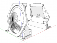
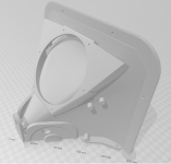
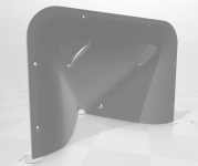
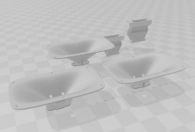
I have designed printed woofer mounts for easily placing the driver exit ports to the sides of the horn. It is positioned for the shortest exit port possible while keeping the sides of the horn as narrow as possible. With 1/2"(15/32") material you can go as small as a 24"w x 15.25"h baffle with four woofers.
They are designed to mount fully inside the enclosure, and have a 1/4" lip inside the mouth for flush trimming the pass-through hole should you desire. I did...
I thought I would put them up here for anyone else who might get an idea from them.
I would suggest at least 2.4mm walls with 30% cubic(or similar) infill. Print with the mouth downward with supports at 50-55deg, as this leaves a large area at the drivers center to be supported, and it can come up through the mouth.
SketchUp and STL files attached
Attachments
Last edited:
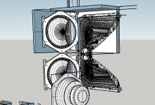
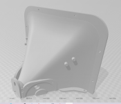
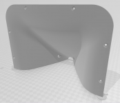
I have made a few alterations to the waveguide STLs bwaslo has graciously provided for us here in this thread.
After printing them out there were a few things I changed to make future prints and installations easier for myself.
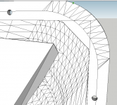
I massaged all the section joining mismatches (got to love fusion,) added a bit more plastic around the cd mounting to horn area, and cut a lip for mounting the horn to the baffle. You just trace the horn out and then inset it 5/8" in from the sides, top and bottom. The come in 1"-5/8" from each corner and draw the diagonal.
I used #6 x 3/8" pan heads for the mids, #6 x 5/8" pan heads for the woofers, two each #8 x 3/4" and #6 x 3"(2.5" would work better but aren't local for me) bolts w/nuts to join the waveguide halves. Then #8 x 3/4" pan heads to mount the waveguide.
I'm making a center for a friend using four of the woofer mounts from the previous post, and I'll post the responses later when life and weather align...
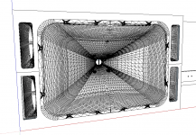
Then I am switching gears and moving to a printed 16" waveguide Small Syns adaptation for myself... Went ahead and did three versions of the horn for future use... My eminence h290b version wasn't bad, but it was always just a place holder for a seos 15 that never turned up...
After printing them out there were a few things I changed to make future prints and installations easier for myself.
I massaged all the section joining mismatches (got to love fusion,) added a bit more plastic around the cd mounting to horn area, and cut a lip for mounting the horn to the baffle. You just trace the horn out and then inset it 5/8" in from the sides, top and bottom. The come in 1"-5/8" from each corner and draw the diagonal.
I used #6 x 3/8" pan heads for the mids, #6 x 5/8" pan heads for the woofers, two each #8 x 3/4" and #6 x 3"(2.5" would work better but aren't local for me) bolts w/nuts to join the waveguide halves. Then #8 x 3/4" pan heads to mount the waveguide.
I'm making a center for a friend using four of the woofer mounts from the previous post, and I'll post the responses later when life and weather align...
Then I am switching gears and moving to a printed 16" waveguide Small Syns adaptation for myself... Went ahead and did three versions of the horn for future use... My eminence h290b version wasn't bad, but it was always just a place holder for a seos 15 that never turned up...
Attachments
-
 Capture11.PNG270 KB · Views: 742
 -
 Capture15.PNG172.6 KB · Views: 725
 -
 Capture13.PNG263.2 KB · Views: 705
 -
 Capture14.PNG228.4 KB · Views: 349
 -
 Capture12.PNG50.5 KB · Views: 363
 -
Horn STL.zip810.3 KB · Views: 250
-
Large bwaslo Horns SKP 1.zip1.4 MB · Views: 259
-
Large bwaslo Horns SKP 2.zip2.5 MB · Views: 260
-
 Capture4.PNG127.6 KB · Views: 443
 -
 Capture16.PNG165.1 KB · Views: 453
Last edited:
Is there anyone who is close to Daytona or Orlando Fl that could help me setup my large format 3d printer, and maybe we could work together on printing some of these horns
I have a printer, but I’m a 100% newbie with this and need the help with setting it up
I have a printer, but I’m a 100% newbie with this and need the help with setting it up
That looks like a good plan. With the woofers, if I were doing it, I'd put the ports on the sides of the speaker. For a smaller baffle size. (Unless of course these were to be flush mounted in a wall).
The messiness of my files isn't really all Fusion's fault, I literally was first learning how to do 3D design while I was making this horn so my workflow was probably about as bad as it gets and I didn't quite understand how the program see points on different sketches.
The messiness of my files isn't really all Fusion's fault, I literally was first learning how to do 3D design while I was making this horn so my workflow was probably about as bad as it gets and I didn't quite understand how the program see points on different sketches.
I really wasnt trying to knock your files. All cad programs have their quirks.
I have had similar issues with fusion. You don't notice anything until you go looking and find a simple looking seam is really a multifaceted micro milimeter sized cavern folded over on itself.
SketchUp like i used here creates duplicate (or quad 😡) faces on top of itself almost at random. I probably still missed a few small ones. Cura was happy though.
Side firing woofers. I have never used a side firing woofer above ~150hz, so the thought never occurred to me. I remember you talking about puting them to the sides, but I was thinking baffle sides not enclosure sides. I might try that too at some point.
The center I posted only has the woofer outputs on the front baffle. It's using four 6fe100s.
It is a sealed enclosure sized to roll off at ~80hz. There was a ported option set to match a fusion tempest 12s output, but the size needed and the fact that it would be used crossed over to multiple F20 horn subs anyways meant that porting was not the way to go.
I had the port exiting in a slot at the top rear firing upwards in this configuration.
I've just found out that the Celestion TF0410MR driver has been archived.. Really sucks since it was the last component I was missing before starting construction of the synergy horn..
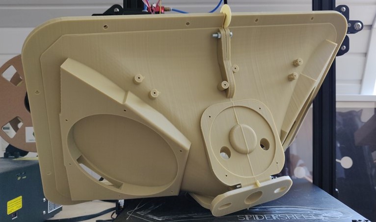
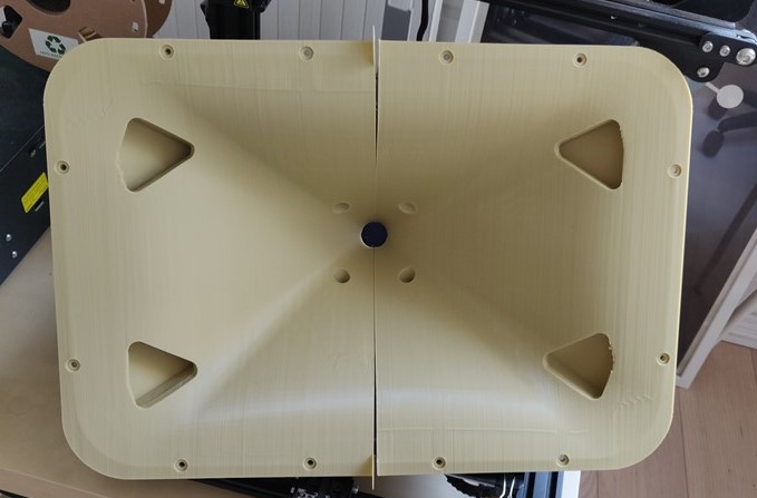
So I finally got to print my own horns. I used to version made by soho54 which removed some of the small error in the file + makes mounting a bit easier. A big thanks to both Bill for designing the speaker and providing the file + to soho54 for cleaning it up.
Since I only have a 0.4 mm nozzle, I had to print with a layer height of 0.25 mm. That meant that each half took 70 hours to print. Quite a lot of that time was spent on me worrying that the print would fail.
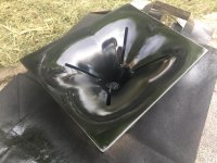
My first print failed halfway through by the horn getting dislodged from the bed. Second attempt was done with glue stick on the bed, which resulted in a perfect print. The last half printed without any problems, until I noticed that the spiderprint (a surface treatment glued to the printers bed) had been pulled up at both diagonal edges of the horn, resulting in a slightly warped print. Since I can't bare think of printing another half, I just think I'm going to fill the 3 mm gap with epoxy and give everything a nice sanding and spraypaint. I don't think it will hurt the performance of the speaker once fixed.
Next up is assembly of the crossover and buying the last drivers before testing and measuring.
Since I only have a 0.4 mm nozzle, I had to print with a layer height of 0.25 mm. That meant that each half took 70 hours to print. Quite a lot of that time was spent on me worrying that the print would fail.
My first print failed halfway through by the horn getting dislodged from the bed. Second attempt was done with glue stick on the bed, which resulted in a perfect print. The last half printed without any problems, until I noticed that the spiderprint (a surface treatment glued to the printers bed) had been pulled up at both diagonal edges of the horn, resulting in a slightly warped print. Since I can't bare think of printing another half, I just think I'm going to fill the 3 mm gap with epoxy and give everything a nice sanding and spraypaint. I don't think it will hurt the performance of the speaker once fixed.
Next up is assembly of the crossover and buying the last drivers before testing and measuring.
Attachments


Last edited:
I'm also in the process of making one of these and am struggling a bit understanding the crossover. Why the notches in the lowpass of the 6FE100's?
- Home
- Loudspeakers
- Multi-Way
- 3D printed 3-way Unity waveguide home audio speaker