I am aiming for an 18" version.
On the right side I cut the corner opposite to the right rear corner for volume compensation. See attachment below.

I do think we can glue vertical (brown) braces on the front like it is, I think you can still squeeze drivers through it. Maybe the center front vertical brace can be made removable the get some room to work inside.
Yes along the front we need extra brace horizontal to attach grill. This will make it more robust.
On the right side I cut the corner opposite to the right rear corner for volume compensation. See attachment below.
I do think we can glue vertical (brown) braces on the front like it is, I think you can still squeeze drivers through it. Maybe the center front vertical brace can be made removable the get some room to work inside.
Yes along the front we need extra brace horizontal to attach grill. This will make it more robust.
Hi USRFobiwan,
I would leave the inside as originally drawn, a little easier to build, and the brace inside that corner acts as an additional seal for the horn path; the outside could have a small reflector, maybe at a similar tilt as the big reflectors in the center?
Regards,
I would leave the inside as originally drawn, a little easier to build, and the brace inside that corner acts as an additional seal for the horn path; the outside could have a small reflector, maybe at a similar tilt as the big reflectors in the center?
Regards,
Thanks Oliver,
Hopefully I can start prototype building near the end of december. Probably going to open new topic TH18SC / TH218SC around the same time. Little confusing to hijack the lab12 hron thread. Maybe a modderator can move these messages to new topic?
Hopefully I can start prototype building near the end of december. Probably going to open new topic TH18SC / TH218SC around the same time. Little confusing to hijack the lab12 hron thread. Maybe a modderator can move these messages to new topic?
I was going to comment earlier today... a thread on a compact 12" design is now the place for a large 18" design? ??
Hi bitSmasher,
That's what I thought, but see Posts #412/413/414.
It would still make sense to have a thread, let's say: Scientific's Carnival Float 18" TH Subs". There is a lot to sort out though.
Regards,
That's what I thought, but see Posts #412/413/414.
It would still make sense to have a thread, let's say: Scientific's Carnival Float 18" TH Subs". There is a lot to sort out though.
Regards,
TH218SC_TRY_1
Hi Y'all,
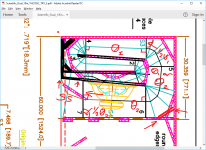
Here is where I'm currently at with my attempt at a tapped horn drawing w/ cone correction. This could use one more run-through, and additional braces, but the sketch is already cluttered enough. It's a large box. 🙂
Regards,
Hi Y'all,
Here is where I'm currently at with my attempt at a tapped horn drawing w/ cone correction. This could use one more run-through, and additional braces, but the sketch is already cluttered enough. It's a large box. 🙂
Regards,
Attachments
Hi Y'all,
Here is where I'm currently at with my attempt at a tapped horn drawing w/ cone correction. This could use one more run-through, and additional braces, but the sketch is already cluttered enough. It's a large box. 🙂
Regards,
To be honest, I wouldn't worry about the cone-compensation, if (1) the impact of that volume has been taken into consideration in the sim, and (2) the impact of that volume does not denigrate the sim'd output of the TH.
That looks really nice Oliver.
I always thought that cone correction has more influence at the higher bands. Well not 'a tought' actually but in my measured response graphs on the Xoc1 TH18 build with cone correction applied (to the driver I used) the result was a slightly flatter response in the > 100 <120hz range. Not much was going on in the usable range of the TH18. But more importantly, the driver seems more stable and we could hear cleaner bass as in less rumbling, although this is pure 'hear/feeling' we got from a/b testing.
I always thought that cone correction has more influence at the higher bands. Well not 'a tought' actually but in my measured response graphs on the Xoc1 TH18 build with cone correction applied (to the driver I used) the result was a slightly flatter response in the > 100 <120hz range. Not much was going on in the usable range of the TH18. But more importantly, the driver seems more stable and we could hear cleaner bass as in less rumbling, although this is pure 'hear/feeling' we got from a/b testing.
Is Hornresp lying about the bottom end? Who knows. But if not, a little crown xti 2000, 4 of these $325 cabinets, some EQ, 136db down to around 35hz....sounds like a party! For cheap too!
What does the simulation look like if you change the Hornresp model segments to parabolic? As built, the box does not have a conical area expansion.
Hi Y'all,
Here is where I'm currently at with my attempt at a tapped horn drawing w/ cone correction. This could use one more run-through, and additional braces, but the sketch is already cluttered enough. It's a large box. 🙂
Regards,
Looks great!
Attachments
Hi BP1Fanatic,
Post #510: "Looks great!"
Thanks. Still working at it: looking again at USFFobiwan's suggestion in Post #501, that would slightly reduce L23, and lengthen L34, combined w/ a slightly larger expansion angle in the L34 segment this would be even closer to the Keystone flare. Add that to the extension in L45, and the TH218SC should be a beast. 🙂
Regards,
Hi USRFobiwan,
Post #508: "... in my measured response graphs on the Xoc1 TH18 build with cone correction applied (to the driver I used) the result was a slightly flatter response in the > 100 <120hz range. Not much was going on in the usable range of the TH18. But more importantly, the driver seems more stable and we could hear cleaner bass..."
It's so good to get some actual information from a person who has built and measured one of these boxes, there has to be a reason why Tom Danley build this into his TH115. A picture that Djim posted (and that was quickly deleted) showed a substantial restriction at the throat entrance into the horn to one side, and into a horn path stub to the other side. The attached drawing is not the picture that was deleted, but a drawing by Djim that shows the principle applied to a symmetrical layout. I'm still working on the details for this layout, and I'm still looking at your suggestion from Post #501, I might be able to use it to improve the match in the TH218SC horn flare to the Keystone flare.
Regards,
Attachments

Last edited:
That looks really nice Oliver.
I always thought that cone correction has more influence at the higher bands. Well not 'a tought' actually but in my measured response graphs on the Xoc1 TH18 build with cone correction applied (to the driver I used) the result was a slightly flatter response in the > 100 <120hz range. Not much was going on in the usable range of the TH18. But more importantly, the driver seems more stable and we could hear cleaner bass as in less rumbling, although this is pure 'hear/feeling' we got from a/b testing.
Cone correction provides for a reduction of the compressible air volume in the throat giving you more "control".
It's so good to get some actual information from a person who has built and measured one of these boxes, there has to be a reason why Tom Danley build this into his TH115.
There might be more than one reason, but one is pretty straightforward - given the folding he used in the TH115 (and TH118), it was possible to include cone compensation and INCREASE the path length and volume of the horn flare at the same time. Because the horn's path is basically perpendicular to that section in the horn, the "cone compensation" ends up extending the horn's path and increasing its volume.
That's not the case for the layout of your own. If you include cone compensation as suggested in your layout, you'll be decreasing the volume of the horn, albeit not by much.
I did some actual experiments with varying cone compensation and also inserting a restriction @ S2 some time back for my POC3 design. See the following threads:
http://www.diyaudio.com/forums/subwoofers/276742-cone-compensation-test-case.html
http://www.diyaudio.com/forums/subwoofers/277035-s2-restriction-test-case.html
The main takeaways from the experiments for me was that HornResp can successfully sim the impact of cone compensation (or the lack thereof) by adjusting the value for Vtc and that you can lose SPL if you over-compensate.
Brian, I do not believe that Tom intended to do a 'cone compensation'. But rather a clever way to lay down the horn path in a compact box. Otherwise they did not need to replace the original driver for another brand. Otherwise cone compensation was used in old W bins, the same triangle wood piece (as shown in the pic in #512) This was also ment to clever layout the path. Not to compensate cones.
Although I never did know about your CC test topic, In my measurements it did almost the same, one build without and one prototype build with CC (no changes in paths). That it did almost nothing for 35<>100h range but above that range it flattened some dips and peaks on the measurement graphs. Like I said before, the difference is noticeable when listening to music, especially on war volumes. Like Neo Dan said, more control.
Cheers
Brian, I do not believe that Tom intended to do a 'cone compensation'. But rather a clever way to lay down the horn path in a compact box.
We do not know if he did or did not design the layout to include cone compensation. However, I'm firmly in the "if it looks like a duck..." group 🙂.
Otherwise they did not need to replace the original driver for another brand.
I don't think that there was any suggestion from Tom that the driver was replaced for another brand due to an issue with the layout of the horn, cone compensation or not. It was due to an issue with the driver.
Which brings up a pet peeve of mine. The "floppiest" part of a driver's cone is at the edge, where it meets the surround. In the car audio subwoofer world, there have been solutions put in place for this for over a decade now. Either ending the cone with a flat flange (e.g. Image Dynamics drivers), or folding it over (JBL, Infinity). Both approaches strengthen the cone's edge significantly. How come this hasn't shown up in the pro audio subwoofer world yet?
Otherwise cone compensation was used in old W bins, the same triangle wood piece (as shown in the pic in #512) This was also ment to clever layout the path. Not to compensate cones.
I suspect that, apart from its aesthetic purpose, that triangle's actual main function was to simply strengthen the wall of the horn at that point. I'd bet that little or no difference in performance would be measured if it was removed from that location and placed on the other side of the panel.
Although I never did know about your CC test topic, In my measurements it did almost the same, one build without and one prototype build with CC (no changes in paths). That it did almost nothing for 35<>100h range but above that range it flattened some dips and peaks on the measurement graphs. Like I said before, the difference is noticeable when listening to music, especially on war volumes. Like Neo Dan said, more control.
My tests with cone compensation also showed a change in the distortion profile for the horn, but chances are that might be because of the driver being mounted slightly differently (it had to be removed and then reinstalled when the cone compensation was added). If reduction in distortion IS an actual feature of a cone-compensated layout, then that, and the change to the upper end of the response where are our ears are a lot more sensitive, could account for the improvement that you heard. IMO a lot more testing would be needed to confirm that distortion reduction is an actual and measurable feature of implementing cone compensation in a design.
Hi Y'all,
Looks like it is not quite clear which benefits can be ascribe to "cone correction", but there seem to be some.
Here is the TH218SC w/ cone correction and USRFobiwan's suggested corner from Post #501. Similar to the Keystone the Hornresp simulations will not be exact. I'm attaching the first sketch w/ some explanations as to the chosen size of the cone correction. A number of boards were doubled up for strength, and to reinforce (and seal) corners. The driver location was choosen to allow a 21" driver at the same S4 location, if only a 18" driver is under consideration the driver can be move closer to S5 for a slightly longer L2--4, and a little shorter L45.
The comparisons are based on the B&C 18TBW100.
Regards,
Attachments
-
TH218SC_Single.txt1,017 bytes · Views: 92
-
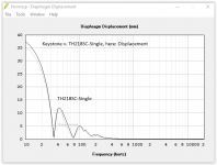 Keystone_v_TH218SC-Single_Displacement.PNG15.6 KB · Views: 445
 -
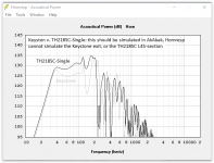 Keystone_v_TH218SC-Single_SPL.PNG23.7 KB · Views: 462
 -
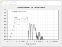 TH218SC_Single_v_Dual_SPL.PNG16.7 KB · Views: 463
 -
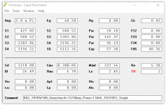 TH218SC-Single_Input.PNG18.9 KB · Views: 471
 -
Scientific_Dual_18in_TH218SC_TRY_3.pdf41.1 KB · Views: 132
Last edited:
Here's some questions and suggestions...
1. I'm not sure of the benefit of having such a wide flare at the horn's mouth for a 100 Hz and below TH. Certainly it seems to be absent from Danley's TH designs, so I suggest perhaps comparing it to an alignment that does not incorporate such a wide flare. With that in mind, here's my suggestions for modifications..
2. Remove the flare as I've indicated in the diagram, extend the internal panels as indicated in the diagram, and adjust the angle of the driver's baffle and the internal panels above it to smooth out the expansion from S1 to S3. Note: this also allows the driver to be moved closer to S1, but also allows the opportunity to have a long S1-S2 to experiment with the use of damping to flatten the horn's response just above its passband - see link below:
http://www.diyaudio.com/forums/subwoofers/296731-ooh-looky-th-does-42hz-500hz-3db.html
3. Make sure all sample points are orthogonal to the center line along the horn as indicated. This should produce slightly more accurate results from the HornResp sim IMO.
4. Experiment with setting the expansion angle at the back of the horn to either the first one used at S2 or the second used at S4, to see which gives the better result. Changing it from the former to the latter will increase the horn's efficiency, but the resonance frequency will move upwards as well. Of course, your horn's layout does allow you to move S3 to the back of the horn, so you can select do do that too 🙂
5. Change the corner braces to simple 45-degree ones. Much easier to implement in practice, and the change in response will likely be negligible.
Attachments
Hi Brian,
You are fast. 🙂
Here is part of my rational: I was trying to get close to original Keystone flare for most of the horn path, and t.hen add an extension.
In my drawing of the Keystone enclosure the flare angle changes from 2.24° (1st section/down) to 3.43° (2nd section/up) to 6.33° (3rd section/top) finally 1° coming back down to the driver, and beyond. Obviously, the Keystone mouth (exit) has something to do w/ all that.
Anyway, in my drawing I'm going from 2.5° to 4° to 10° back to 4° (driver baffle) to the big mouth/extension angles. If I use less than 10° for the section between S3 and 6 the area @ 6 does not correspond to the flare (all this started w/ a given exterior dimension).
The big mouth seems to improve the output in the upper passband with only minor loss at the low end. This is something I might try to address in the next revision, but, if I increase the path length I'll have to reduce the individual section flare angles to make the horn fit the given dimensions (as you well know, it's kind of a Chinese puzzle...). Obviously, I could keep the general mouth frontal area, and reduce the depth without loosing to much...?
Thanks for thinking through this, all good comments.
Regards,
- Home
- Loudspeakers
- Subwoofers
- $325 Lab 12 based PA tapped horn ~ 35Hz extension