Depends on the phase response of what goes above, and frequency of the crossover.Hi
What should I set the delay on the DSP for this design?
Generally you will delay the top cabinets by roughly the time of flight of the horn path.
Put top and sub on the ground, balance level between the two at crossover frequency with measurement mic/dB meter equidistant between cabinets about 2 meters away outdoors away from large objects on the ground.
Start with around 7ms top delay, reverse polarity on the sub, adjust up or down looking for the maximum null at the crossover frequency. Put polarity back to normal, the pair should be about 6 dB louder at the crossover point than either one individually. If you have ended up around 0ms or 14ms delay the polarity is probably incorrect, the top or sub lagging by one wavelength at the crossover point.
If you have a dual FFT test unit, the phase trace will be smooth through the crossover region.
Last edited:
Probably. The LAB12 sims half decent in smaller designs but the low corner really suffers. LAB12 is decent in the THAM15 which is about same volume but different layout. It's one of those preferences type things, what is easier for you to move/stack? Taller rectangular or shorter square. The LAB12 was tested in this design and that trumps all untested things, so the PAL12 is a proven winner in my book.
The THAM15 looks like it might be easier to move around. Did they just replace the 15" with the LAB12 or are the dimensions different as well?
Same dimensions, I just used the LAB 12 for the sim instead of the 15. I just did a sim shootout of the 2 and as expected the PAL12 digs lower but the THAM15 is 2-3db higher. I got a little excited being reminded the PAL12 is a mid 30hz design and was hopeful simming a higher end driver would rid the saddle shaped response and get more output but no dice...
Hi Y'all,
Let's not get too excited, as I said in Post #451:... 1W into Re the SPL curves are almost identical...
A lot of the DSL curves are measured 28.3V @ 10m into "whatever"; so, the nice high output of the 21SW152 is the equivalent: Eg=2.83 into Re=3.3Ohm.
If you really care about what the driver is doing you need to go into the SPL graph, and use the Sample tool in Hornresp, and step through the frequency range of interest. An alternative is 1W into Re, I think it does reflect what's going on better than some nominal 4 or 8 Ohm value. One argument for just using 2.83V on everything is that most modern amplifiers have a lot of excess current capability, and (within reason) pretty much don't care, they'll just amplify the incoming voltage.
That's why I like to post the Hornresp Export file, that way everyone can look at the data any which way they want to.
I'm done w/ the basic drawing update, but have not had time to do anything else. I decided against reducing the depth, so it will stay @ D=31.875". So the box will be 42x24x31-7/8". It would theoretically be possible to reduce the cross-sectional areas of the horn, and save a little depth, etc. but everytime you reduce the box size you loose some SPL (or low end extension) so I think this is it. I start adding individual board locations/dimensions, hopefully I'll post these later, or tomorrow.
Regards,
Hi Oliver,
It's been a while but I'm back. I built a cab and did a quick subjective test and compared it with a Th18. We need to agree a name for this cab. It's a beast. I suggest TH18SC ? - for Scientific. Or SC118. Are you OK with that? I'm trying to attach a pic but I'm having some issues.
Scientific
Hi Scientific,
TH18SC sounds good to me. Hope you can find a way to post a few pictures. 🙂
Regards,
TH18SC sounds good to me. Hope you can find a way to post a few pictures. 🙂
Regards,

Hi Scientific,
TH18SC sounds good to me. Hope you can find a way to post a few pictures. 🙂
Regards,
Oliver
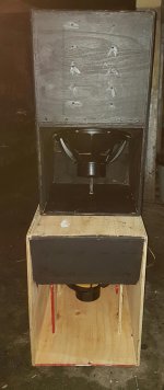
I tried to attach 2 pics. Let's see if this works.
We used the 18SW115-8 driven by and FP14000. In our quick test, the TH18SC appeared to sound almost the same as the TH18 until the deep bass comes. We played 'One Dance' by Drake and then in the chorus you suddenly hear a low bass note come from nowhere and just rumble the house. It was strange as I had listened to that song so many times and never knew it had those low notes. You get a glimpse of it in the TH18 but the TH18SC just brings it out. I will do some more comparisons later and try to plot the response.
Scientific
Attachments
Ref.: Post #455/491
Hi Scientific,
Thanks for the pictures, and the first review.
Looks like you can use them vented in two different positions as planed (out front and out the bottom)? Maybe someday you can try the box w/ the blue (cyan) squashed Keystone mouth as shown in the drawing, you may get even a little more lows.
Nice to see some wood with the drawings. 🙂
Regards,
Awesome! Can we do something about the middle divider. Does it need to be like this or can I extend it to the start of the drivers and continue with bracing.
Hi USRFobiwan,
Post #493: "...itching to build a TH218SC..."
Sounds like a plan. 🙂
Regards,
Nice plan tb46! !
Awesome! Can we do something about the middle divider. Does it need to be like this or can I extend it to the start of the drivers and continue with bracing.
Do rods like the spl guys in car audio.
Hi USRFobiwan,
Post #495: "...Can we do something about the middle divider...."
Yes, most certainly. You need support in the middle/mouth section of the box, and this sketch just takes two TH18SC, and connects them together. A number of removable braces in this section, and a 2x2 brace around the perimeter of the mouth would be a good start, and-as BP1Fanatic suggests in Post #497-1"Dia. wood dowels can be inserted, and made removable.
I have been working on a very similar box w/ a maximum dimension of 60" so that the wood cuts fit better on 5'x5' plywood (I know it's bad practice to design to the plywood edge, so maybe I can find another 1/2" somewhere?). That one will also have the option of cone compensation as has been talked about in numerous threads. One thing I thougt about is to add a removable center section, so that two boxes can be screwed together, or a bottom can be added to each individual box. T-nuts and 1/4" flat head allen bolts on 6" center to hold the mess together? I'm not sure how this would play w/ the forces at work when going full power into one of these modern drivers though. Might take a while to get all this worked out... 🙂
Regards,
This is my take on it. Since we need to be able to replace drivers. And extra vertical braces in the mouth area. Also added bracing options. Left slightly different bracing than the right. I also wanted to strengthen the back corners with some bracing or wood triangle.

Last edited:
Hi USRFobiwan,
Yes, that looks like a good first try, corner blocking/bracing of some kind will definitely help, but, we don't want to loose too much volume. Maybe those vertical mouth braces can be made removable by gluing battens to the top and bottom boards, and using those to attach the braces? A 2x2 edge around the mouth could be used to attach a metal grill for further stiffening? Are you shooting for the 21" or the 18" version?
Regards,
- Home
- Loudspeakers
- Subwoofers
- $325 Lab 12 based PA tapped horn ~ 35Hz extension