Hi Brian,
It's hard for me to get the exact meaning:
Keystone thread, Post #25: "...I think many upright fold TH which have the final exit making a roughly 90 degrees turn would benefit from the Keystone mouth, whether or not the driver is located at the very end (mouth) of the horn.
The Keystone shaped exit would probably offer no advantage in the type of tapped horns where the final segment is pointed forward with the driver located at the mouth."
- To me that means Art sees possible benefit in case of a mouth perpendicular to the path. For a layout as in #433 he does not predict any advantage for the Keystone mouth.
Keystone thread, Post #26: "...The Keystone shape, with the horn's fold orientation, allows a compromise between a “too large” and “too small” opening.
Too large an opening provides more upper response with less low end, too small makes for a lower LF corner but less upper response."
- I interpret this that he found the smaller Keystone mouth to be favoring the low end, and then there are the graphs in Post #46...
But either way, the maximum exit as in #433 at the end of the horn path seems to have a distinct advantage over the passband, and very nearly the same low frequency output as per Hornresp. There still would be the possibility of the modified Keystone mouth in the normal Keyston position which Scientic has used as a comparison (I wish he had some frequency response graphs on that.).
Just remembered something: I might be able to apply the EXP flare for the S2 to S3 section in Hornresp, and then see what the intermediate cross-sectional areas at the turns would be, which would give me the individual board angles. Onward. 🙂
Regards,
Hi Brian,
It's hard for me to get the exact meaning:
Keystone thread, Post #25: "...I think many upright fold TH which have the final exit making a roughly 90 degrees turn would benefit from the Keystone mouth, whether or not the driver is located at the very end (mouth) of the horn.
The Keystone shaped exit would probably offer no advantage in the type of tapped horns where the final segment is pointed forward with the driver located at the mouth."
- To me that means Art sees possible benefit in case of a mouth perpendicular to the path. For a layout as in #433 he does not predict any advantage for the Keystone mouth.
Have a look at post #36, where Art goes into some detail concerning why he thinks the KS approach works - http://www.diyaudio.com/forums/subw...ing-18-15-12-inch-speakers-4.html#post2537534
Keystone thread, Post #26: "...The Keystone shape, with the horn's fold orientation, allows a compromise between a “too large” and “too small” opening. Too large an opening provides more upper response with less low end, too small makes for a lower LF corner but less upper response."
This is what I'd expect to happen if the CSA at the mouth is decreased. Once you start restricting the mouth like this, Fb goes down and the pass-band changes, similar to what happens when you downshift Fb for a bandpass alignment by lengthening the vent.
I quite like where Oliver's going with his design, though I may opt for a constant expansion through S1 to S3, and then adjusting S4 and S5 as shown in the attached diagram:
What would be the effect of continuing the expansion at the proper horn flare rate until S5 is practically the whole width/height of the cabinet? Would we get a lower fb, or increased SPL or both?
From my playing in hornresp when you make the mouth larger you gain some spl above the knee but CAN lose some extension. Now you can gain on the whole BW if you make the mouth very large. But arent you going away from the keystone exit?
Sounds like your looking at trying a S5 of about 7000-.
Sounds like your looking at trying a S5 of about 7000-.
What would be the effect of continuing the expansion at the proper horn flare rate until S5 is practically the whole width/height of the cabinet? Would we get a lower fb, or increased SPL or both?
Efficiency should increase, bandwidth should decrease and Fb will go up.
Hi Scientific,
Post #443: "...the effect of continuing the expansion at the proper horn flare rate until S5 is practically the whole width/height of the cabinet?..."
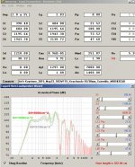
In Post #416 you can find the drawings, and Hornresp export files for the Keystone refold MOD#3. Part of that are three different mouth configurations: S5=2130.72 / S5=2535.09 / S5=2791.71.
Just as an example I'm attaching a Hornresp TH Wizard window showing a comparison between S5=2130, S5=3500 and S5=6000cm^2. The new capture and display feature in the Wizard now allows us to display three curves. A cool feature. As you can see the gain in the upper passband is accompanied by a loss at the low end.
Regards,
Post #443: "...the effect of continuing the expansion at the proper horn flare rate until S5 is practically the whole width/height of the cabinet?..."
In Post #416 you can find the drawings, and Hornresp export files for the Keystone refold MOD#3. Part of that are three different mouth configurations: S5=2130.72 / S5=2535.09 / S5=2791.71.
Just as an example I'm attaching a Hornresp TH Wizard window showing a comparison between S5=2130, S5=3500 and S5=6000cm^2. The new capture and display feature in the Wizard now allows us to display three curves. A cool feature. As you can see the gain in the upper passband is accompanied by a loss at the low end.
Regards,
Attachments
Great post. Thanks. I spent some time making sure I understood it and discussed it with my team.
The output with S5=6000 is preferred as it has some gain in the 70-80Hz area which will help the kick in live performances while there is no significant loss around 40 Hz. At 30 Hz it would be about 5 db less than the original box with S5 2130 cm^2. We could use some equalization for that.
However the maximum S5 with the current dimensions would be 4437 cm, unless if we decide to increase the height of the cab from 37.87" (809.6) to 42" (1077.66). The sim would be between the red and the green on your chart. But for us every db counts. What we need to know now is how best to expand S5 to 6000 while keeping the flare rate reasonable and keeping the height within 42". See attachments. Now all this is without keystone exit.
Would a 21" driver add a few DBs and also lower the fb? One gentleman achieved both by just changing the driver in a DSL TH115 from a 15 to an 18. All parameters of the cab (s2, s3 path length) remained practically the same. (This has always amazed me). When contacted, the guy said he got around 3db more output. Both the 15 he replaced and the 18 were 4 ohms so his comparison was easy. He has some info here.
https://soundforums.net/threads/1205...115-to-a-TH118
I still have a liking for your shortened version of the cab with the Keystone exit so I guess at the end of the day we will have to build two different cabs and do comparisons.
Attachments
Hi Scientific,
Post #447: "...we need to know now is how best to expand S5 to 6000 while keeping the flare rate reasonable and keeping the height within 42". See attachments. Now all this is without keystone exit."
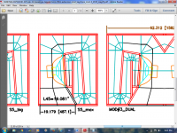
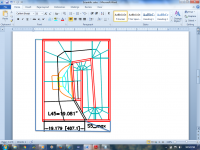
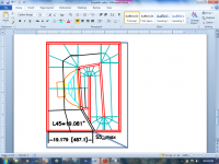
I'll attach an expansion of MOD#3 to a height of 42", this allows to cary the mouth all the way across the "bottom" of the cabinet, and results in a 4430cm^2 S5 (mouth). The expansion is only downward, so the rest stays the same. This should still allow you to experiment w/ the Keystone exit on the "front" face.
I'm also attaching the Hornresp file export. The additonal L45 provides you with so much additional output (maybe a little much @ the upper end) that I would call it a good compromise.
I'm a little pressed for time right now, but if you decide on a specific version let me know, and I'll add all the additional dimensions.
Regards,
Post #447: "...we need to know now is how best to expand S5 to 6000 while keeping the flare rate reasonable and keeping the height within 42". See attachments. Now all this is without keystone exit."
I'll attach an expansion of MOD#3 to a height of 42", this allows to cary the mouth all the way across the "bottom" of the cabinet, and results in a 4430cm^2 S5 (mouth). The expansion is only downward, so the rest stays the same. This should still allow you to experiment w/ the Keystone exit on the "front" face.
I'm also attaching the Hornresp file export. The additonal L45 provides you with so much additional output (maybe a little much @ the upper end) that I would call it a good compromise.
I'm a little pressed for time right now, but if you decide on a specific version let me know, and I'll add all the additional dimensions.
Regards,
Attachments
Oliver, I was trying to do the simulation using Hornresp and your txt file parameters but ran into some issues when inputting L data. I am most likely doing something wrong as it is not accepting the lengths. Anyway we are interested in the last June 1 version with the mouth 4430cm^2, so when you get a chance, add the dimensions for us. That would be much appreciated.
From the looks of it, it does not appear that there is enough baffle board space for a 21 so I guess our options with this one would be limited to an 18.
From the looks of it, it does not appear that there is enough baffle board space for a 21 so I guess our options with this one would be limited to an 18.
Hi Scientific,
I'll try to get to it later today.
Meanwhile, take mod3x42.txt (that is the Hornresp simulation for the drawing in Post #448) from Post #448, and copy and paste it into the Hornresp Import folder. Then you should be able to import it into Hornresp as a Hornresp Record. Then you can use the Add button to make additional copies for changing drivers, etc.
It should be possible to increase the length of the baffle board to allow for a 21" driver, the box is already wide enough, so it's just a matter of increasing the length of the baffle board, etc... There is also the question how that will play in the simulation. I'll look @ that too, but it will be later.
Regards,
Attachments
Hi Scientific,
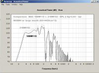
I did a quick Hornresp simulation comparing the 18SW115 w/ the 21SW152 (note to self: that's 152 not 112, so stop typing 112 you.........). Using 1W into Re the SPL curves are almost identical w/ a small advantage (flatter curve) going to the 21". Using Eg=2.83 the 21" is the clear "winner". I'll attach the graph.
It will take me a little while to get the drawing updated, I guess I'll call that one MOD#4, and it will allow for the 18" and the 21" driver. The box will be H42"xW24"xD~30.5". It should still be possible to use a (modified?) Keystone exit on the original front of the box.
Regards,
Attachments
Hi Scientific,
I did a quick Hornresp simulation comparing the 18SW115 w/ the 21SW152 (note to self: that's 152 not 112, so stop typing 112 you.........). Using 1W into Re the SPL curves are almost identical w/ a small advantage (flatter curve) going to the 21". Using Eg=2.83 the 21" is the clear "winner". I'll attach the graph.
It will take me a little while to get the drawing updated, I guess I'll call that one MOD#4, and it will allow for the 18" and the 21" driver. The box will be H42"xW24"xD~30.5". It should still be possible to use a (modified?) Keystone exit on the original front of the box.
Regards,
If it is BC 152 - 4 ohm driver Eg = 2,00 volts not 2,83 for 2 Pi and if BC 115 - 8 ohm then Eg = 2,83 volts is correct for 2 Pi then put those numbers in and the attach graph will be different!
Hi Scientific,
I did a quick Hornresp simulation comparing the 18SW115 w/ the 21SW152 (note to self: that's 152 not 112, so stop typing 112 you.........). Using 1W into Re the SPL curves are almost identical w/ a small advantage (flatter curve) going to the 21". Using Eg=2.83 the 21" is the clear "winner". I'll attach the graph.
Regards,
Well that 21 inch simulation really caught my attention. I have not seen a TH simulation on the forum with such high SPL while still having 100 db authority at 33 Hz. Is this an 8 ohm vs 8 ohm comparison ? I know B&C makes both 4 ohm 8 ohm versions in both the 18 and the 15. Let's double check this. As of now I am very excited.
Correction . The post should have said 'I know B&C makes both 4 ohm 8 ohm versions in both the 18 and the 21.'
Hi Y'all,
Let's not get too excited, as I said in Post #451:... 1W into Re the SPL curves are almost identical...
A lot of the DSL curves are measured 28.3V @ 10m into "whatever"; so, the nice high output of the 21SW152 is the equivalent: Eg=2.83 into Re=3.3Ohm.
If you really care about what the driver is doing you need to go into the SPL graph, and use the Sample tool in Hornresp, and step through the frequency range of interest. An alternative is 1W into Re, I think it does reflect what's going on better than some nominal 4 or 8 Ohm value. One argument for just using 2.83V on everything is that most modern amplifiers have a lot of excess current capability, and (within reason) pretty much don't care, they'll just amplify the incoming voltage.
That's why I like to post the Hornresp Export file, that way everyone can look at the data any which way they want to.
I'm done w/ the basic drawing update, but have not had time to do anything else. I decided against reducing the depth, so it will stay @ D=31.875". So the box will be 42x24x31-7/8". It would theoretically be possible to reduce the cross-sectional areas of the horn, and save a little depth, etc. but everytime you reduce the box size you loose some SPL (or low end extension) so I think this is it. I start adding individual board locations/dimensions, hopefully I'll post these later, or tomorrow.
Regards,
Attachments
Would there be any benefits to build this more complex modified keystone compared to Brians TH in post #424? Approx same size, but a lot fewer details.
Last edited:
Hi Osse,
For comparison you may want to put both into Hornresp?
I think Brians in Post #424 was based on the 1st try in Post #404, which led to Post #416 where you have a drawing, and 3 different versions, going from the simple one to bigger mouth versions, and slightly more complex wood layouts. This includes Hornresp simulations for all three versions. This led to a request for maximizing the mouth opening which led to MOD#4 in Post #455 where you'll find added corner reflectors, and in Post #457 additional bracing.
It's an interesting question what would happen if you take MOD#4, remove the corner reflectors, and use just one board from the driver baffle to the mouth opening.
For enclosures that are purpose build for portable very high power usage a little extra wood should not be a big problem. DSL seems to route (groove) the locations for all the divider baffles. That and glueing and screwing would also be a good idea (remember to add the groove depth to the internal width). So where do you stop? By the way, MOD#4 still need bracing in the mouth opening(s) that is not yet in the drawings.
Maybe AkAbak simulations could come close for comparison purposes, but an honest answer to your question would probably involve building and measuring.
Regards,
Last edited:
- Home
- Loudspeakers
- Subwoofers
- $325 Lab 12 based PA tapped horn ~ 35Hz extension