@6thplanet
To understand the directivity and the influence of the horn you can EQ the speaker to flatten its on-axis response (0°), then remeasure. The new measurements will show a flat response on-axis, while deviations off-axis reveal how the speaker’s directivity behaves. As shown above, I’ve taken measurements both with and without EQ. Does that make sense?
To understand the directivity and the influence of the horn you can EQ the speaker to flatten its on-axis response (0°), then remeasure. The new measurements will show a flat response on-axis, while deviations off-axis reveal how the speaker’s directivity behaves. As shown above, I’ve taken measurements both with and without EQ. Does that make sense?

Still had my default smoothing on from the sub measurements. Here are the important ones unsmoothed. Gated at 2.5ms.


13 years ago I had a toddler vs ultra slim speaker problem too. I wanted a minimalist look without plates or outriggers so I came up with a rather odd, drastic to some, mounting solution. Once I had settled on exact speaker placement I secured the hardwood flooring to the subfloor with screws and routed out a large key hole in the floor under each speaker then made an aluminum flange that bolted onto the center of the speaker base. The speakers dropped into the key hole and slid back to lock into place. They could not be moved but rotated if needed. When we sold the house I had to plug the holes in the floor but it wasn't very hard to grain match the bland even grained maple and refinish those spots.
Am I Chasing the Last 1%?
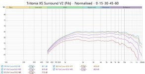
Encouraged by the measurements of the roundover surround I added to the Tritonia XS, I’m now trying to adapt that performance into a version that fits my printer bed (180×180 mm). Ideally, I’d like to print it all in one piece.
The Tritonia XS is 140 mm wide, which gives me 20 mm to work with on each side. I experimented with a 20 mm roundover followed by a larger curve that wraps toward the back. To shape the transition, I (somewhat naively and superstitiously) used the Fibonacci sequence to grow from 20 mm to 32.3 mm.
New profile (printable in one piece):


 - Normalised - 0-15-30-45-60.jpg")
Comparison: 25 mm radius roundover surround:

There’s very little between them in terms of performance - but is it enough to justify the effort?
Can this be fully resolved, or have I officially lost the plot?
Would love to hear from others who have dabbled in this 🙂
Encouraged by the measurements of the roundover surround I added to the Tritonia XS, I’m now trying to adapt that performance into a version that fits my printer bed (180×180 mm). Ideally, I’d like to print it all in one piece.
The Tritonia XS is 140 mm wide, which gives me 20 mm to work with on each side. I experimented with a 20 mm roundover followed by a larger curve that wraps toward the back. To shape the transition, I (somewhat naively and superstitiously) used the Fibonacci sequence to grow from 20 mm to 32.3 mm.
New profile (printable in one piece):
Comparison: 25 mm radius roundover surround:
There’s very little between them in terms of performance - but is it enough to justify the effort?
Can this be fully resolved, or have I officially lost the plot?
Would love to hear from others who have dabbled in this 🙂
Attachments
@Illusus Yes, I know the feeling. As I get older and time becomes more of a premium, it gets harder to strike the right balance. I went into the sub build specifically with the idea that I would not sweat the petty things.
But I guess it comes down to one question: does it really matter?
One of the sub grilles is 0.6 mm lower than the others.
It's there. It lurks.
IT CONSUMES ME.
But I guess it comes down to one question: does it really matter?
- Am I bothered because others might notice and think my handiwork is less than I believe it is? If so, that's pride.
- Is it a genuine effort to achieve the best for myself? Then it's a question of effort versus result, and where diminishing returns start to creep in.
- Or have we just lost perspective? Maybe this is self-sabotage disguised as misunderstood perfectionism, stopping us from enjoying the process.
One of the sub grilles is 0.6 mm lower than the others.
It's there. It lurks.
IT CONSUMES ME.
Midwoofers...
So, I have a handful of contenders:
Thoughts, anyone?
It’s tricky to find one that will fit the 157 mm wide baffle and the 121 mm internal width of the box.
So, I have a handful of contenders:
Faital Pro 5FE120
Pros- Cheap (around £25)
- Easy to replace, which makes leaving it uncovered less risky for little fingers
- Decent distortion measurements
- But not the best distortion performance
- Low WAF
18 Sound 5W430
Pros- Mid-priced (around £50)
- Aluminium cast basket
- Better distortion numbers than the Faital
- Will need a grille
- No demodulation ring
BMS 5S117
Pros- Excellent distortion performance
- Pairs well with a compression driver
- Quite expensive (£100)
- Will definitely need a grille
- Distortion rises sharply around my intended crossover (120 Hz)
- High Fs
Thoughts, anyone?
It’s tricky to find one that will fit the 157 mm wide baffle and the 121 mm internal width of the box.
Cheap Experiments, Cube Resonances, and 3D Printed Threads


Bit of a mixed bag today - part pleased, part forehead-slappingly annoying.
I plumped for the Faital 5FE120 as a cheap experiment to play with. To keep things compact, I decided to crop the back of the slim tower design and ended up with a small 2L (1.5L net) sealed enclosure. That pushed the system Q up to 0.90, but I figured with decent damping (I used Rockwool) I could pull that down toward 0.7. I managed 0.74 in the end, which is close enough.
What I didn’t quite plan for was the resonance issue around 930 Hz and 1 kHz. Despite the stuffing, I’ve got lingering energy visible in both the frequency response and the impedance sweep - neither of which are present in the raw driver measurements. The damping definitely helped, but it didn’t eliminate it entirely.
I mean, I knew I would get a super strong standing wave because of the cube but this is nuts.
Is it the driver or is it the box?

---


vs.


Nothing shows on the datasheet and I'm struggling to find measurements that are detailed enough elsewhere.
What’s odd is that with a 121mm cubed box, I expected the primary standing wave to be around 1.4 kHz, but I’m not seeing any evidence of that. Instead, these lower frequency smears are dominant. If anyone has a theory on what might be going on there, I’m all ears.
On a brighter note, the horn/baffle transition is coming along nicely, and I should be able to get some farfield measurements tomorrow. Also - and this might be obvious to everyone else - I just discovered you can 3D print threads. I added one to the base frame of the horn support, which now screws up snug against the compression driver body to take strain off the horn’s face. Just a prototype for now, but I think I’ll need to add some gussets or a vertical brace to keep everything rigid.

Anyway, I really like how it's beginning to look, it vaguely reminds me of the Vivid Audio Kaya speakers. Prototype took around 15 hours of printing and I think the nozzle came loose towards the end.
PS. Excuse my "damples". It's been a long day.
Bit of a mixed bag today - part pleased, part forehead-slappingly annoying.
I plumped for the Faital 5FE120 as a cheap experiment to play with. To keep things compact, I decided to crop the back of the slim tower design and ended up with a small 2L (1.5L net) sealed enclosure. That pushed the system Q up to 0.90, but I figured with decent damping (I used Rockwool) I could pull that down toward 0.7. I managed 0.74 in the end, which is close enough.
What I didn’t quite plan for was the resonance issue around 930 Hz and 1 kHz. Despite the stuffing, I’ve got lingering energy visible in both the frequency response and the impedance sweep - neither of which are present in the raw driver measurements. The damping definitely helped, but it didn’t eliminate it entirely.
I mean, I knew I would get a super strong standing wave because of the cube but this is nuts.
Is it the driver or is it the box?
---
vs.
Nothing shows on the datasheet and I'm struggling to find measurements that are detailed enough elsewhere.
What’s odd is that with a 121mm cubed box, I expected the primary standing wave to be around 1.4 kHz, but I’m not seeing any evidence of that. Instead, these lower frequency smears are dominant. If anyone has a theory on what might be going on there, I’m all ears.
On a brighter note, the horn/baffle transition is coming along nicely, and I should be able to get some farfield measurements tomorrow. Also - and this might be obvious to everyone else - I just discovered you can 3D print threads. I added one to the base frame of the horn support, which now screws up snug against the compression driver body to take strain off the horn’s face. Just a prototype for now, but I think I’ll need to add some gussets or a vertical brace to keep everything rigid.
Anyway, I really like how it's beginning to look, it vaguely reminds me of the Vivid Audio Kaya speakers. Prototype took around 15 hours of printing and I think the nozzle came loose towards the end.
PS. Excuse my "damples". It's been a long day.
Diagonal waves, perhaps?If anyone has a theory on what might be going on there, I’m all ears.
German, but very detailled:I'm struggling to find measurements that are detailed enough elsewhere.
https://www.hifi-selbstbau.de/index.php/hsb-datenblaetter/tief-mittelt/faital-5fe120-8?showall=1
This is FAQ # 682Is it the driver or is it the box?
A:
“The first step in looking at any speaker system, is to take nearfield measurements of the individual driver outputs. This tells you what the driver is doing and removes almost all of the room acoustics effects and some of the cabinet affects. Doing anything else first is a waste of time”
Reference: Jack Hidley ; who's probably forgotten more things that I know.
DIY 101: Take the driver out, put your mic up as close as possible the cone/dome e.g. < radius / 2; and re-measure.
-neither of which are present in the raw driver measurements
Is it the driver or is it the box?
I have used the 5FE100 and 5FE120 in the past, and I will use them again because of their cost performance and ability to handle some power
I am puzzled by your box result, but there is no arguing with the impedance blip at 1KHz. Did you chamfer the driver mounting hole at the rear?
Maybe some more running in would help or a different microphone position will show it in a lessened way
I have attached a screenshot of what I measured some time ago with the driver in a small cabinet 8 by 11 inch. 12dB/octave full range, and approx 2.5mS and gated 12dB/octave.
In my case I think the breakup was the hardest bit to push down as much as possible whilst still trying to get 2.5-3KHz out of the driver to hand over to a small 19mm tweeter, in your case this should be a non issue as I assume you are handing over to your HF driver by 2kHz or below.
Attachments
Something resonating at ~1k, if box is smaller than that it's no internal resonance but something else. The whole box could be it, not the walls resonating but the whole object. It could possibly excite the table it sits on for example. Maybe the waveguide rings symphatetically with the box, or something like that. Blip on impedance plot could still be seen even though sound wasn't coming from inside the box, the woofer is a microphone while you do impedance sweep, and any external sound source is recorded and shows as blip.
You can test this stuff quite fast, just using the impedance measurement and see what happens to the blip at 1kHz:
Perhaps it's something else, simple debugging like this should help to find it.
You can test this stuff quite fast, just using the impedance measurement and see what happens to the blip at 1kHz:
- remove the waveguide
- change how the box is coupled to table, or any fixture yo have it sit on
- measure driver free air
Perhaps it's something else, simple debugging like this should help to find it.
VituixCAD Woe, 5FE120 Handshake Issues and Confusion³
Tried to cram this into my lunch break while working from home. First time using VituixCAD for a real project (I usually rely on X-Sim 3D). Spent a good hour chasing my tail before realising you have to set your DSP system in the config. That one caught me out.
Anyway, on to the results.
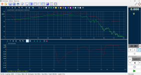
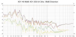
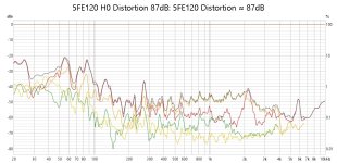
The nearfield measurement confirms a blip around 1 kHz, so I’m not imagining things. Still, I can't explain why this enclosure shows zero standing waves in the expected regions. The spectrogram is clear, but the behaviour doesn't align with what I expected from this box shape. The distortion of the 5FE120 correlates with the mesurements that @stv very kindly linked above. A 2khz spike et al...


This is all still using the prototype horn and cabinet, so it's more academic than anything at this stage.
Crossover is set to LR24 at 2 kHz, and it's very obvious where the 5FE120 hands off to the compression driver. I’m beginning to question whether this driver is the right fit. Maybe I’m just being reactive, but it's got me thinking.


Much better horizontal polars than I expected though – very happy with those. No downward slope in H0 yet, might do that to taste when listening.
Tried to cram this into my lunch break while working from home. First time using VituixCAD for a real project (I usually rely on X-Sim 3D). Spent a good hour chasing my tail before realising you have to set your DSP system in the config. That one caught me out.
Anyway, on to the results.
The nearfield measurement confirms a blip around 1 kHz, so I’m not imagining things. Still, I can't explain why this enclosure shows zero standing waves in the expected regions. The spectrogram is clear, but the behaviour doesn't align with what I expected from this box shape. The distortion of the 5FE120 correlates with the mesurements that @stv very kindly linked above. A 2khz spike et al...
This is all still using the prototype horn and cabinet, so it's more academic than anything at this stage.
Crossover is set to LR24 at 2 kHz, and it's very obvious where the 5FE120 hands off to the compression driver. I’m beginning to question whether this driver is the right fit. Maybe I’m just being reactive, but it's got me thinking.
Much better horizontal polars than I expected though – very happy with those. No downward slope in H0 yet, might do that to taste when listening.
Attachments
Midbass Woofer Widening Woes
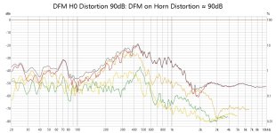
I'm not massively happy with the distortion performance of the Faital Pro 5FE120, but it does excel in one area: directivity. In my particular setup, its dispersion closely matches the horn (but could be better below 2k)

The core issue I’m wrestling with is a balancing act that pivots around SD.
So far, the list of viable options is pretty short:
If anyone has usable distortion measurements for the B&C or Scan-Speak units, I’d love to see them. Otherwise, the 18 Sound 5W320 seams the awkward but best-balanced option for now.
I'm not massively happy with the distortion performance of the Faital Pro 5FE120, but it does excel in one area: directivity. In my particular setup, its dispersion closely matches the horn (but could be better below 2k)
The core issue I’m wrestling with is a balancing act that pivots around SD.
- If SD is too large, I can’t physically fit the driver on the baffle.
- If SD is too small, the directivity narrows too late (around 1-2 kHz), leading to a mismatch with the horn’s dispersion and a less cohesive polar response.
So far, the list of viable options is pretty short:
- 18 Sound 5W320
Slightly better distortion than the 5FE120 and a similar SD. One of the more practical alternatives. - Seas U16RCY/P (H1520-08)
Mixed opinions on this one. I’ve seen comments suggesting distortion near the crossover point isn’t great. - Scan-Speak 15W/8434G00
Would be an extremely tight squeeze on the baffle, and once again, I’m struggling to find reliable distortion measurements. - B&C 5FG44
With 95 cm² SD, it could improve directivity even further. Unfortunately, no published distortion data that I can find.
If anyone has usable distortion measurements for the B&C or Scan-Speak units, I’d love to see them. Otherwise, the 18 Sound 5W320 seams the awkward but best-balanced option for now.
Have you considered this one ?
https://www.bmsspeakers.com/index.php-39.html?id=bms_5s117
It seems to me it has everything you're after.
On the other hand - disliking 5fe120 distortion curve is one thing, but how does it sound ?
https://www.bmsspeakers.com/index.php-39.html?id=bms_5s117
It seems to me it has everything you're after.
On the other hand - disliking 5fe120 distortion curve is one thing, but how does it sound ?
Last edited:
- Home
- Loudspeakers
- Multi-Way
- 3-Way Co-ax Floorstander