Amazing result there @6thplanet !
Not sure I have patience in me for that atm, but something to try at some point, for sure!
Not sure I have patience in me for that atm, but something to try at some point, for sure!

Exactly (scroll down for anodizing)!home anodizing
How did you get those phase plugs so incredibly red? Great looking!
Hell yeah @stv ! Anodizing a dome tweeter, cool!
Those soaked in the dye for about a week and a half.
That whole process was a learning experience! It failed twice before that, I can't stress enough how freaking clean the parts need to be.
Those are the drivers that ended up in the speakers Parts Express chose for the cover of the 2014 catalog.

Hijack, over. @grahamgraham , definitely put it on your list of tricks to learn. It's very rewarding when you get it right.🤘🏼
Those soaked in the dye for about a week and a half.
That whole process was a learning experience! It failed twice before that, I can't stress enough how freaking clean the parts need to be.
Those are the drivers that ended up in the speakers Parts Express chose for the cover of the 2014 catalog.
Hijack, over. @grahamgraham , definitely put it on your list of tricks to learn. It's very rewarding when you get it right.🤘🏼
@6thplanet your twice failure and then great success is exactly why I need A LOT more time to do this! 100% will later in life tho! Great job.
Outriggers complete!
Finish (in order of application):


I forgot to order any rubber sheet for the bottoms of the screw feet, so in a bit of a panic, I realized I had a few spare inner tubes lying around. Sliced 'em up and contact glued 'em on - these babies are now running on Continental Race 28s, FYI. Less than 1mm thick and has some ribs for grip.
Each foot is locked in place with a nylon washer and a domed cap nut.


Finish (in order of application):
- Hycote Etch Primer
- Hycote Matte Black Spray Paint
- Rust-Oleum Crystal Clear Spray Top Coat
I forgot to order any rubber sheet for the bottoms of the screw feet, so in a bit of a panic, I realized I had a few spare inner tubes lying around. Sliced 'em up and contact glued 'em on - these babies are now running on Continental Race 28s, FYI. Less than 1mm thick and has some ribs for grip.
Each foot is locked in place with a nylon washer and a domed cap nut.
After the excitement of machining aluminium from a 3D print, I started wondering about getting my own machine. Turns out, if I had just 10 parts printed by someone else the cost would basically cover a Bambu Lab A1 Mini - so I got a bit overexcited and bought one.
My first functional print was a set of brackets for the back of the cabinets, to tie cables to:


My first functional print was a set of brackets for the back of the cabinets, to tie cables to:
Looking really good!
I need a set of these outriggers myself. Should have asked you to make a duplicate set for me, and for you - to recover the cost by selling it to me!
The painted finish on the box is really nice.
I need a set of these outriggers myself. Should have asked you to make a duplicate set for me, and for you - to recover the cost by selling it to me!
The painted finish on the box is really nice.
@AlmaAtaKZ Thanks!
More than happy to do a print for you if you'd like one! Then quite simple to shape on some flat bar stock.
More than happy to do a print for you if you'd like one! Then quite simple to shape on some flat bar stock.
Installed but I won't be able to do any proper measurements for the crossover to the Genelecs until next week... Cable tie brackets working overtime until I make the MF/HF units.
Genelecs screwed on with some spacers and washers I printed (currently loving the ability to make random spec. parts on demand)
Wife happy with the less dominating footprint.


Genelecs screwed on with some spacers and washers I printed (currently loving the ability to make random spec. parts on demand)
Wife happy with the less dominating footprint.
Looking for Tips: Subwoofer Integration Workflow
Next week I’m planning to do all the measurements needed to design the crossover from my Genelecs to the subwoofers - at least until I get around to building the MF/HF units.
Historically, my attempts at this haven’t gone that smoothly. Results have always felt like a bit of a lottery. I’ve picked up a lot more experience since I last tackled this so I’m hoping for a better outcome this time.
Target crossover area: 90-150 Hz
I’d really appreciate it if anyone could share their best practices for integrating subwoofers - specifically around measurement and crossover design.
Any tips, corrections, or alternate methods welcome. Thanks!
Next week I’m planning to do all the measurements needed to design the crossover from my Genelecs to the subwoofers - at least until I get around to building the MF/HF units.
Historically, my attempts at this haven’t gone that smoothly. Results have always felt like a bit of a lottery. I’ve picked up a lot more experience since I last tackled this so I’m hoping for a better outcome this time.
Target crossover area: 90-150 Hz
I’d really appreciate it if anyone could share their best practices for integrating subwoofers - specifically around measurement and crossover design.
Questions:
- Do I need a reference timing signal from a separate speaker when using REW?
- How critical is phase matching in this frequency range?
My current approach:
- Take measurements at three positions (left/middle/right on the sofa) and average to form one measurement each for subs and tops.
- Measure both subs and tops with L+R channels active (forming a combined mono response)
- Load into VituixCAD, design crossover, copy settings to MiniDSP, remeasure, compare, listen… repeat ad infinitum.
Any tips, corrections, or alternate methods welcome. Thanks!
Last edited:
I don't know your genelec model but I believe it should have a high pass filter from 80 Hz. It's available via a dipp switch on the backside.
If you don't mind doing the crossover again whenever you change positioning or other fundamental stuff, MSO is pretty ideal for finding the crossover and minimizing room modes
Nice to see another DIYer who also has fierce room gain deal with it with open eyes and not try to pretend it's not there!
Integration
Well, that was much less painful than I remembered. The REW phase alignment tool made it a doddle.
I’ve been enjoying the 4020Cs, so I didn’t want to stray too far from them - just sneak the subs in underneath. I think it worked quite nicely: LR24 at 120 Hz with a 6 ms delay on the subs.
The subs were a little heavy during listening, so I knocked them down by 3 dB (not shown here).
There’s still some disruption in the 150–300 Hz range but it’s not as severe as in my previous setup (see post 1).
Next: Midwoofer!
The spec for this is pretty simple - a slim bezelled 5" midwoofer that will do well from 100-2500hz, sealed.
I only have one for the shortlist so far which is the Faital Pro 5FE120. It's worringly cheap yet has all the requirements.
https://faitalpro.com/en/products/LF_Loudspeakers/product_details/index.php?id=401010110
Is there a better performer out there?
I never really shared my thoughts on the sound after integrating the subs. It’s honestly incredible what a bit of low end extension can do to make a system sound massive. It definitely doesn’t sound like the compact setup it is... which means I’m on track toward my goal!
Thanks to everyone for your contributions so far. I'm excited to move on to the next stage! 🙂

Big thanks to my wife for putting up with the speaker tomb slowly forming for future domestic archaeologists to one day unearth.

Thanks to everyone for your contributions so far. I'm excited to move on to the next stage! 🙂
Big thanks to my wife for putting up with the speaker tomb slowly forming for future domestic archaeologists to one day unearth.
Nice!
You can send all your drivers to me, I’ll be happy to accept that you pay the postage also😇 That said, I never had WAF issues regarding size or state of finish! Chose with care and background checks😅
You can send all your drivers to me, I’ll be happy to accept that you pay the postage also😇 That said, I never had WAF issues regarding size or state of finish! Chose with care and background checks😅
Smaller  , Deeper , Wider ???
I was browsing the ATH4 Horn Design thread for the thousandth time last week, hyping myself up to take the plunge. While looking through the designs @mabat had for sale, I messaged him about a smaller, wider version of his very popular and well-measuring Tritonia horn. And, well.... Joy, jubilation, delight! Big thanks to Marcel!
His designs can be bought here: the 3D models of mbatik


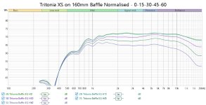
This horn could be both the solution and a fun challenge for my project. Marcel noted that these horns are designed to be used with a carefully considered baffle, so I started thinking about how to implement it into the narrow 157mm baffle planned. I quickly (lol) mocked up a 25mm radius roundover surround on the 3D printer, made a surface-mount recess on a test cabinet, and ran some measurements.
Freestanding horn:


25mm Radius Surround Freestanding:


Baffle flush mount:


The freestanding surround seems to perform best, though the difference between it and the baffle-mounted version is minor. If I go with the freestanding setup, I’ll need a clever design to work around the limited 180x180x180mm bed size of my A1 Mini, as I’d like to print the horn and surround as one piece.
There's good linear separation in both configurations, with a bit of diffraction around 5.5kHz - but it's only about 1dB of bunching, so hardly noticeable. Both are wider than any horn I’ve used or looked at so far.
Crossing over from a 5" midbass around 2kHz should be easy.
But is the difference between radius surround and baffle mount enough?
, Deeper , Wider ???I was browsing the ATH4 Horn Design thread for the thousandth time last week, hyping myself up to take the plunge. While looking through the designs @mabat had for sale, I messaged him about a smaller, wider version of his very popular and well-measuring Tritonia horn. And, well.... Joy, jubilation, delight! Big thanks to Marcel!
His designs can be bought here: the 3D models of mbatik
This horn could be both the solution and a fun challenge for my project. Marcel noted that these horns are designed to be used with a carefully considered baffle, so I started thinking about how to implement it into the narrow 157mm baffle planned. I quickly (lol) mocked up a 25mm radius roundover surround on the 3D printer, made a surface-mount recess on a test cabinet, and ran some measurements.
- Peerless DFM-2535R00-08 compression driver.
- All measurements were taken at 80cm with a 4.25ms gate.
- Unfortunately distortion measurements were mostly obscured by noise floor.
- Normalisation, when applied, is between 1,000-10,000hz
Freestanding horn:
25mm Radius Surround Freestanding:
Baffle flush mount:
The freestanding surround seems to perform best, though the difference between it and the baffle-mounted version is minor. If I go with the freestanding setup, I’ll need a clever design to work around the limited 180x180x180mm bed size of my A1 Mini, as I’d like to print the horn and surround as one piece.
There's good linear separation in both configurations, with a bit of diffraction around 5.5kHz - but it's only about 1dB of bunching, so hardly noticeable. Both are wider than any horn I’ve used or looked at so far.
Crossing over from a 5" midbass around 2kHz should be easy.
But is the difference between radius surround and baffle mount enough?
Attachments
- Home
- Loudspeakers
- Multi-Way
- 3-Way Co-ax Floorstander