Actually as a general rule, a vented design has more group delay than a sealed design but I've attached what WinISD shows for the Satori. Grey is vented and yellow is sealed, so the general rule applies here. Note however at what frequencies the differences happen anyways and then ask yourself when used as a mid in a 3-way, what frequencies end up not being used?
Also, the transient response is generally better in a sealed vs vented design. I'd probably go with a Q somewhere around .5 to .6 as that gives you some extra volume to add stuffing to better absorb the rear wave. Or to perhaps employ a physical strategy something like shown here (sans the vent) - http://www.humblehomemadehifi.com/download/Humble%20Homemade%20Hifi_Concertino.pdf. And as an aside, I would also consider doubling up the side and top walls to the mid enclosure too as I believe you have the extra volume available to play with and the added mass will make it harder to excite the mid chamber resonances.
I like the idea of doubling up the mid chamber. Good call! 🙂 I'm still a little confused about group delay. I'm seeing the same as you between the sealed vs ported in WinISD. However my understanding of group delay is; that its the delay each driver will have at any single moment in time. So if the ported woofer has a 10ms delay vs a sealed mid, that might be audible. Isn't ideal setup, where all the drivers have the same group delay? Sorry if i've miss understood.
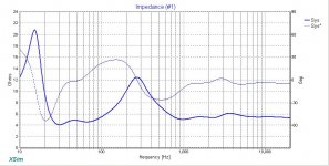
Looking at the mid group delay in comparison to the woofer is a valid point so let's do that. Blue is the woofer this time and we don't exceed a 2ms difference between the woofer and the sealed mid until we get below about 60Hz. (Looks like a may have used a different vented alignment for the Satori on my last post - I don't remember what it was.This time it's in 5L tuned to 41.5Hz. The sealed mid is in 4.5L and the woofer is in 20L tuned to 35Hz.)
Expect the woofer/mid xo point to be around 300Hz to 400Hz. If you go 2nd order acoustic, the mid will be down about 6dB at the xo point, another 12dB an octave below that (at about 150Hz) and another 12dB another octave below that, at about 75Hz. So the mid in comparison to the woofer will be about 30dB quieter by the time the group delay between the 2 drivers starts to diverge by more than 2ms.
Conclusion: it's not something to be concerned about. Go sealed. Or if you really feel adamant about it, go vented but stuff it so really you'll be going aperiodic. Troels is one person among others seems to have a preference for this type of mid alignment in a 3-way.
Attachments
Is it "possible" to get the woofer to perform in a sealed enclosure as well as it would do in a ported enclosure? The OCD in me is kicking in and if I sealed both the Woofer and Mid (in separate compartments), the group delay would be spot on.. I know that under X frequency the groups delay shouldn't be noticeable but... 🙂
A passive radiator is very similar to a ported cabinet and performs in pretty much the same way. Certainly there is no real reason to go with a PR over a port when the port dimensions are manageable. Usually PRs are used when tuning frequencies are low and cabinets are small. This would require a port of very long dimensions, too long to actually fit inside the cabinet, so a PR is used.
While it is true that the group delay of a ported cabinet is higher than that of a sealed do not let it worry you. Some argue that the group delay isn't even audible at low frequencies unless really excessive.
In other words a correctly designed ported cabinet will offer excellent bass quality. This has been my experience and usually the room interaction is at fault, when people compare ported vs sealed, rather than the loudspeaker, as to ones preferences.
With your loudspeaker design ported is absolutely necessary if you want decent bass extension and I would not recommend going any other way.
Yes, I concur. Going sealed on the woofer would negate one of your primary design goals of achieving the lowest possible response you can get in that cabinet in order to watch movies without a sub.
Maybe this is a shortcoming on my part but I usually don't even look at group delay. So that should tell you how much I worry about it in a typical design. I had to go back to WinISD which I hardly ever use (I don't actually like the user interface) and re-learn the darned thing just so I could analyse what you were concerned about.
So ease your mind, and let it be concerned with more important things.
Many thanks both 🙂 You have set my mind at rest. I'll have some revised/corrected data tomorrow based on the current (ported Woofer and sealed Mid) design 🙂
Hey Guys, Sorry for the late reply. I've been bogged down with work 🙁
I've re ran the response modeler for the Tweeter. How does that look now?
https://drive.google.com/file/d/0Bwwef9FGi6GiUkVzM1oyOHZMalE/view?usp=sharing
p.s. i'm really struggling with this part of the process. I'm making changes but have no idea why i'm making them, which is difficult for me to get my head around. Worst case if i can't get my head around this bit, can you help with the simmed - phased data, so that we can move on the the cross-over work? 🙂
Last edited:
You should make sure that once you trace a frequency or impedance response that you plot it and give it a quick visual check to see if it matches the original.
This time your FR is correct except for the tail portion which deviates @ 300Hz (that looks like a tracing error) but unfortunately your zma looks like it may be from another tweeter. The resonance peak and the level are both off from the original.
As I suggested previously, if you have the time it's best to go through this step by step, but since you don't and also because you will hopefully in the end be using the actual in-cabinet measurements to design the xo, I've attached the files I came up with for you to play around with in XSim. And in truth, there is sometimes some guess work involved in the file creation process. Where and at what level to splice the box responses can be either very straightforward or a bit confusing depending on what the actual driver's FR looks like. With these drivers, I'm finding that both FR's make it a bit ambiguous so I've chosen to make the conservative choice in terms of the splicing SPL level but it could in reality be a little bit off and that is where real measurements aid considerably.
To use the files, simply remove the .txt file extension.
Lastly, if you use XSim, you'll need to input delay data for the mid and the woofer. Use these (although there is a little guesstimation here too in terms of the drivers' acoustic centers):
tweeter = 0
mid = 1.1"
woofer = 2.67"
Attachments
-
Peerless HDS Al 6.5in Z + phase modified 20L Fb=33Hz.zma.txt13.2 KB · Views: 72
-
Satori Z + phase modified CB 4L.zma.txt13 KB · Views: 60
-
SB 29RDNC Z + phase.zma.txt1.3 KB · Views: 58
-
RM Peerless Wfr.frd.txt13.7 KB · Views: 53
-
RM Satori.frd.txt13.5 KB · Views: 62
-
RM SB29.frd.txt13.6 KB · Views: 51
You should make sure that once you trace a frequency or impedance response that you plot it and give it a quick visual check to see if it matches the original.
This time your FR is correct except for the tail portion which deviates @ 300Hz (that looks like a tracing error) but unfortunately your zma looks like it may be from another tweeter. The resonance peak and the level are both off from the original.
As I suggested previously, if you have the time it's best to go through this step by step, but since you don't and also because you will hopefully in the end be using the actual in-cabinet measurements to design the xo, I've attached the files I came up with for you to play around with in XSim. And in truth, there is sometimes some guess work involved in the file creation process. Where and at what level to splice the box responses can be either very straightforward or a bit confusing depending on what the actual driver's FR looks like. With these drivers, I'm finding that both FR's make it a bit ambiguous so I've chosen to make the conservative choice in terms of the splicing SPL level but it could in reality be a little bit off and that is where real measurements aid considerably.
To use the files, simply remove the .txt file extension.
Lastly, if you use XSim, you'll need to input delay data for the mid and the woofer. Use these (although there is a little guesstimation here too in terms of the drivers' acoustic centers):
tweeter = 0
mid = 1.1"
woofer = 2.67"
Thank you jReave, you're a star! With regards to the 300Hz issue, this is because in Response Modeler I spliced at 300Hz. I'm little confused as to when this splicing is required or not, however lets move on 🙂
I'll being looking at XSim this coming week, my schedule is a little work heavy again..
Just for laughs (i needed to put a little fun back into the project), I measured my existing loudspeakers. If you recall they are Mordaunt Short 914's, which I did an "upgrade" on a few years back.. my first attempt as Loudspeaker modification 🙂
Here are the measurements @ 1M, 0 Degrees, with no smoothing
Dayton Audio DC28FT-8 1-1/8" Silk Dome Truncated Tweeter
Dayton Audio DS175-8 6-1/2" Designer Series Woofer Speaker 8 Ohm
Dayton Audio XO2W-2K 2-Way Crossover 2,000 Hz
https://drive.google.com/file/d/0Bwwef9FGi6GiOGZPc3M3amNjaG8/view?usp=sharing
Interesting the Woofer isn't far of the Dayton FR graphs. The tweeter is quite different though.. That's probably in part due to how I fitted the tweeter into the existing space. Also, there's rather large dip starting at 2k - 5k!
Last edited:
If I'm reading your measurement right, which I'm not at all sure of because it looks like there are actually 2 very different measurements there at the same time, but if I am, it looks like:
1) baffle step loss has not been accurately compensated for
2) the tweeter level needs to be padded down a touch
3) phase alignment in the 2k-5k region might be a problem. You might try reversing the polarity on the tweeter and seeing if that changes the dip there but somehow I doubt that will fix things.
The drawbacks of a stock xo......
If I'm reading your measurement right, which I'm not at all sure of because it looks like there are actually 2 very different measurements there at the same time, but if I am, it looks like:
1) baffle step loss has not been accurately compensated for
2) the tweeter level needs to be padded down a touch
3) phase alignment in the 2k-5k region might be a problem. You might try reversing the polarity on the tweeter and seeing if that changes the dip there but somehow I doubt that will fix things.
The drawbacks of a stock xo......
The graph contained FR, Phase and Distortion. I've now coloured the graph to make that more obvious.. Distortion is in red and phase is the dotted line.
https://drive.google.com/file/d/0Bwwef9FGi6GiSEN3TE5VOUxFb2s/view?usp=sharing
Yeah the stock XO isn't ideal 🙂 I'm not going to play around with the old build. Rather i'll just use the measurements for reference, also I just wanted to see how well my original loudspeaker hack performed. Interesting, they sound better than the stock Mordaunt Short 914's!
Just a thought about the baffle calcs. When I add a grill frame, won't this effect the FR calcs? Can this be ignored at this stage...? as once the driver are in installed, real world measurements will be taken?
Well, first ask yourself whether you can hear any difference with your current speakers with or without the grills?
If the answer is negative, then you have nothing to worry about.
If the answer is positive, then the cloth is likely attenuating some of the high frequencies which should get taken care of when you measure and/or voice the speakers. Or in other words, still not something to worry about for now.
If the answer is negative, then you have nothing to worry about.
If the answer is positive, then the cloth is likely attenuating some of the high frequencies which should get taken care of when you measure and/or voice the speakers. Or in other words, still not something to worry about for now.
Well, first ask yourself whether you can hear any difference with your current speakers with or without the grills?
If the answer is negative, then you have nothing to worry about.
If the answer is positive, then the cloth is likely attenuating some of the high frequencies which should get taken care of when you measure and/or voice the speakers. Or in other words, still not something to worry about for now.
I like the simplicity of this approach 🙂 I can't hear any difference with grills fitted, so I have nothing to worry about then 🙂
Here's my first XO attempt. I've picked a 3rd order design with 3 octave spread. The XO's are 312.5/2500
I've manged to get the XO points correct (I think) but I'm not sure how to flatten the overall level. Can you give me some pointers on this?
I've attached my XSim for this design.
https://drive.google.com/file/d/0Bwwef9FGi6GicEs2QmRITmVfTTg/view?usp=sharing
XSim

Reference for the XO values

I've manged to get the XO points correct (I think) but I'm not sure how to flatten the overall level. Can you give me some pointers on this?
I've attached my XSim for this design.
https://drive.google.com/file/d/0Bwwef9FGi6GicEs2QmRITmVfTTg/view?usp=sharing
XSim
Reference for the XO values
Lpads are traditionally used to pad down drivers to level match. These are placed at the drivers terminals before the xover.
For what it's worth, when simulating with jReave's provided files I had to use an impedance notch filter on the bass driver to flatten the first impedance peak, otherwise it interacted badly with the low pass.
For what it's worth, when simulating with jReave's provided files I had to use an impedance notch filter on the bass driver to flatten the first impedance peak, otherwise it interacted badly with the low pass.
Lpads are traditionally used to pad down drivers to level match. These are placed at the drivers terminals before the xover.
For what it's worth, when simulating with jReave's provided files I had to use an impedance notch filter on the bass driver to flatten the first impedance peak, otherwise it interacted badly with the low pass.
Thanks 5th, the notch filer has really helps with the woofers impedance 🙂
I've also added a resistor to the tweeter which as brought down the level. I'd tried this previously but was conscious that i'm dropping the output level of the tweeter rather than trying to increase the levels of the mid and woofer. Is there a way to do that?
Updated XSim
https://drive.google.com/file/d/0Bwwef9FGi6GieGdtemdzLXNJak0/view?usp=sharing
Result

Try the following:
In the Frequency Response chart:
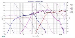
1) in the Scale tab, change the Min Frequency to 10Hz and the vertical center to about 75dB so that you can see the whole frequency range and so you can see more of each driver's roll-off
2) in the Curves tab, choose not to show the phase curve for the system response and choose to show the phase curve for each individual driver instead.
The result should look something like the 1st chart below.
Now here are your 3 goals that need to be juggled at the same time:
1) a flat frequency response
2) good phase alignment for the woofer and mid in the lower xo region (ie. for about an octave above and below the xo point) and the same for the mid and tweeter at the upper xo point
3) a minimum impedance that stays above anything that makes your receiver unhappy. So if your receiver is fine with 4ohm speakers, the minimum is about 3ohm. If it's only happy with 8ohm speakers, your minimum is about 6ohm. Currently, your minimum is at about 2ohm at about 2300Hz. Not so good.
Next you need to set your target responses for each driver. There are several ways to do this with XSim. The one I use involves importing them from Response Modeler.
1) First you have to determine what SPL level to set them at, which is more or less determined here by your woofer's unfiltered response level at about 100Hz. So about 81dB.
2) Next you need to determine what acoustic slopes you should use and at about what xo points. None of these drivers have any severe frequency range limitations, so I would choose all 2nd order Linkwitz-Riley targets except for the tweeter where you typically need asymmetric slopes with the mid in order to get the phase alignment right. So maybe 3rd or 4th order for the tweeter. In terms of the xo points, it's a mistake to lock yourself into predetermined points - you have to let your drivers FR's and phase curves guide you into what is going to work best. So to start off with, think in terms of target xo point ranges, so maybe 300 to 400Hz at the bottom end and maybe anywhere from about 2000 to 3000Hz for the top end.
3) Now in RM, up in the top module, use the High Pass and Low Pass filter sections to create your targets. Play with them a bit to first understand how they work. Then select a LP LR2 at 350Hz, press the Load Coefficient Values button and then use the User Adjustable dB level spinners to bring the level down to 81dB. Then save the result to an frd file. Do the same for a HP LR4 curve at 2500Hz at 81dB, save it and then use both a HP LR2 at 350Hz and a LP LR2 at 2500Hz at the same time with the peak level at 80dB for your mid target.
4) Now back in Xsim, drag and drop 3 new drivers somewhere onto your work grid but do not wire them up in any way, shape or form. Instead simply import your 3 newly saved target files, one for each new driver and then use the "(driver only)" choice in the Response Chart's Curve tab for those drivers to display them.
Now you will attempt to match your driver responses to the target responses (you can be a little flexible here especially with the tweeter) while at the same time keeping in mind the other 2 goals I stated above (phase alignment and minimum impedance).
And here are a few suggestions:
1) ignore that calculator you have attached in post #136 and simply start playing with component values until you get the results you want (or if you have to, use it for starting points and then start adjusting to improve them).
2) try to keep your parts count to a minimum if you can. So don't go to 3rd order electrical for 2nd order acoustic slopes unless you absolutely have to. Usually for a speaker with all the drivers on a flat baffle, 3rd order electrical is only needed on the tweeter in order to properly align the tweeter/mid phase responses. Second order should do everywhere else. Having simmed with this tweeter more than a few times, you may find that 4th order electrical can also work well.
3) if you want to cascade your caps, feel free, but for the sake of the sim keep it simple - just use the single, total capacitor value in your simming and then when you're ready to start buying, then break them down into the smaller values.
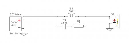
4) I believe your mid has a resonance peak at about 8000Hz which you should take care off. Use a 'tank' filter, a very small capacitor and resistor in series, placed in parallel to the mid's series inductor (see 2nd chart below). You may also need to use a notch filter on the mid's somewhat hilly behavior between about 700Hz and 1200Hz.
5) I also think an impedance flattening filter is required for that Peerless. Try some smaller values though, like 9mH, 550uF and about 6ohm total.
6) Experiment with some small resistance in your 2nd order parallel legs (the shunt leg to ground) if you are having trouble matching your target slopes. They target the 'knee' area of the roll-off and can fine tune phase as well. Quite useful sometimes. For eg., in your sim your woofer is suffering from some peaking at about 300Hz just before it starts to roll-off.
7) In a 3-way, it is quite common to have to reverse the polarity on 1 or 2 of the drivers in order to get the phase alignment correct. Depending on your xo, try reversing the polarity on the tweeter, the mid, or both.
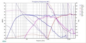
As an overall target you should be looking for something like the last 2 charts below.
PS. Or if your time is still limited, I can simply post the xo that I came up with to help you along but you seem to want to at least start off by doing it yourself.
Cheers
In the Frequency Response chart:
1) in the Scale tab, change the Min Frequency to 10Hz and the vertical center to about 75dB so that you can see the whole frequency range and so you can see more of each driver's roll-off
2) in the Curves tab, choose not to show the phase curve for the system response and choose to show the phase curve for each individual driver instead.
The result should look something like the 1st chart below.
Now here are your 3 goals that need to be juggled at the same time:
1) a flat frequency response
2) good phase alignment for the woofer and mid in the lower xo region (ie. for about an octave above and below the xo point) and the same for the mid and tweeter at the upper xo point
3) a minimum impedance that stays above anything that makes your receiver unhappy. So if your receiver is fine with 4ohm speakers, the minimum is about 3ohm. If it's only happy with 8ohm speakers, your minimum is about 6ohm. Currently, your minimum is at about 2ohm at about 2300Hz. Not so good.
Next you need to set your target responses for each driver. There are several ways to do this with XSim. The one I use involves importing them from Response Modeler.
1) First you have to determine what SPL level to set them at, which is more or less determined here by your woofer's unfiltered response level at about 100Hz. So about 81dB.
2) Next you need to determine what acoustic slopes you should use and at about what xo points. None of these drivers have any severe frequency range limitations, so I would choose all 2nd order Linkwitz-Riley targets except for the tweeter where you typically need asymmetric slopes with the mid in order to get the phase alignment right. So maybe 3rd or 4th order for the tweeter. In terms of the xo points, it's a mistake to lock yourself into predetermined points - you have to let your drivers FR's and phase curves guide you into what is going to work best. So to start off with, think in terms of target xo point ranges, so maybe 300 to 400Hz at the bottom end and maybe anywhere from about 2000 to 3000Hz for the top end.
3) Now in RM, up in the top module, use the High Pass and Low Pass filter sections to create your targets. Play with them a bit to first understand how they work. Then select a LP LR2 at 350Hz, press the Load Coefficient Values button and then use the User Adjustable dB level spinners to bring the level down to 81dB. Then save the result to an frd file. Do the same for a HP LR4 curve at 2500Hz at 81dB, save it and then use both a HP LR2 at 350Hz and a LP LR2 at 2500Hz at the same time with the peak level at 80dB for your mid target.
4) Now back in Xsim, drag and drop 3 new drivers somewhere onto your work grid but do not wire them up in any way, shape or form. Instead simply import your 3 newly saved target files, one for each new driver and then use the "(driver only)" choice in the Response Chart's Curve tab for those drivers to display them.
Now you will attempt to match your driver responses to the target responses (you can be a little flexible here especially with the tweeter) while at the same time keeping in mind the other 2 goals I stated above (phase alignment and minimum impedance).
And here are a few suggestions:
1) ignore that calculator you have attached in post #136 and simply start playing with component values until you get the results you want (or if you have to, use it for starting points and then start adjusting to improve them).
2) try to keep your parts count to a minimum if you can. So don't go to 3rd order electrical for 2nd order acoustic slopes unless you absolutely have to. Usually for a speaker with all the drivers on a flat baffle, 3rd order electrical is only needed on the tweeter in order to properly align the tweeter/mid phase responses. Second order should do everywhere else. Having simmed with this tweeter more than a few times, you may find that 4th order electrical can also work well.
3) if you want to cascade your caps, feel free, but for the sake of the sim keep it simple - just use the single, total capacitor value in your simming and then when you're ready to start buying, then break them down into the smaller values.
4) I believe your mid has a resonance peak at about 8000Hz which you should take care off. Use a 'tank' filter, a very small capacitor and resistor in series, placed in parallel to the mid's series inductor (see 2nd chart below). You may also need to use a notch filter on the mid's somewhat hilly behavior between about 700Hz and 1200Hz.
5) I also think an impedance flattening filter is required for that Peerless. Try some smaller values though, like 9mH, 550uF and about 6ohm total.
6) Experiment with some small resistance in your 2nd order parallel legs (the shunt leg to ground) if you are having trouble matching your target slopes. They target the 'knee' area of the roll-off and can fine tune phase as well. Quite useful sometimes. For eg., in your sim your woofer is suffering from some peaking at about 300Hz just before it starts to roll-off.
7) In a 3-way, it is quite common to have to reverse the polarity on 1 or 2 of the drivers in order to get the phase alignment correct. Depending on your xo, try reversing the polarity on the tweeter, the mid, or both.
As an overall target you should be looking for something like the last 2 charts below.
PS. Or if your time is still limited, I can simply post the xo that I came up with to help you along but you seem to want to at least start off by doing it yourself.
Cheers
Attachments
Last edited:
Try the following:
In the Frequency Response chart:
1) in the Scale tab, change the Min Frequency to 10Hz and the vertical center to about 75dB so that you can see the whole frequency range and so you can see more of each driver's roll-off
2) in the Curves tab, choose not to show the phase curve for the system response and choose to show the phase curve for each individual driver instead.
The result should look something like the 1st chart below.
Now here are your 3 goals that need to be juggled at the same time:
1) a flat frequency response
2) good phase alignment for the woofer and mid in the lower xo region (ie. for about an octave above and below the xo point) and the same for the mid and tweeter at the upper xo point
3) a minimum impedance that stays above anything that makes your receiver unhappy. So if your receiver is fine with 4ohm speakers, the minimum is about 3ohm. If it's only happy with 8ohm speakers, your minimum is about 6ohm. Currently, your minimum is at about 2ohm at about 2300Hz. Not so good.
Next you need to set your target responses for each driver. There are several ways to do this with XSim. The one I use involves importing them from Response Modeler.
1) First you have to determine what SPL level to set them at, which is more or less determined here by your woofer's unfiltered response level at about 100Hz. So about 81dB.
2) Next you need to determine what acoustic slopes you should use and at about what xo points. None of these drivers have any severe frequency range limitations, so I would choose all 2nd order Linkwitz-Riley targets except for the tweeter where you typically need asymmetric slopes with the mid in order to get the phase alignment right. So maybe 3rd or 4th order for the tweeter. In terms of the xo points, it's a mistake to lock yourself into predetermined points - you have to let your drivers FR's and phase curves guide you into what is going to work best. So to start off with, think in terms of target xo point ranges, so maybe 300 to 400Hz at the bottom end and maybe anywhere from about 2000 to 3000Hz for the top end.
3) Now in RM, up in the top module, use the High Pass and Low Pass filter sections to create your targets. Play with them a bit to first understand how they work. Then select a LP LR2 at 350Hz, press the Load Coefficient Values button and then use the User Adjustable dB level spinners to bring the level down to 81dB. Then save the result to an frd file. Do the same for a HP LR4 curve at 2500Hz at 81dB, save it and then use both a HP LR2 at 350Hz and a LP LR2 at 2500Hz at the same time with the peak level at 80dB for your mid target.
4) Now back in Xsim, drag and drop 3 new drivers somewhere onto your work grid but do not wire them up in any way, shape or form. Instead simply import your 3 newly saved target files, one for each new driver and then use the "(driver only)" choice in the Response Chart's Curve tab for those drivers to display them.
Now you will attempt to match your driver responses to the target responses (you can be a little flexible here especially with the tweeter) while at the same time keeping in mind the other 2 goals I stated above (phase alignment and minimum impedance).
And here are a few suggestions:
1) ignore that calculator you have attached in post #136 and simply start playing with component values until you get the results you want (or if you have to, use it for starting points and then start adjusting to improve them).
2) try to keep your parts count to a minimum if you can. So don't go to 3rd order electrical for 2nd order acoustic slopes unless you absolutely have to. Usually for a speaker with all the drivers on a flat baffle, 3rd order electrical is only needed on the tweeter in order to properly align the tweeter/mid phase responses. Second order should do everywhere else. Having simmed with this tweeter more than a few times, you may find that 4th order electrical can also work well.
3) if you want to cascade your caps, feel free, but for the sake of the sim keep it simple - just use the single, total capacitor value in your simming and then when you're ready to start buying, then break them down into the smaller values.
4) I believe your mid has a resonance peak at about 8000Hz which you should take care off. Use a 'tank' filter, a very small capacitor and resistor in series, placed in parallel to the mid's series inductor (see 2nd chart below). You may also need to use a notch filter on the mid's somewhat hilly behavior between about 700Hz and 1200Hz.
5) I also think an impedance flattening filter is required for that Peerless. Try some smaller values though, like 9mH, 550uF and about 6ohm total.
6) Experiment with some small resistance in your 2nd order parallel legs (the shunt leg to ground) if you are having trouble matching your target slopes. They target the 'knee' area of the roll-off and can fine tune phase as well. Quite useful sometimes. For eg., in your sim your woofer is suffering from some peaking at about 300Hz just before it starts to roll-off.
7) In a 3-way, it is quite common to have to reverse the polarity on 1 or 2 of the drivers in order to get the phase alignment correct. Depending on your xo, try reversing the polarity on the tweeter, the mid, or both.
As an overall target you should be looking for something like the last 2 charts below.
PS. Or if your time is still limited, I can simply post the xo that I came up with to help you along but you seem to want to at least start off by doing it yourself.
Cheers
My receiver is good to 4ohm, so your impedance levels give me a little headroom based on a 3ohm min 🙂
Ok so I understand around 50% of what you have posted (which is a big step forward from where I was a month or so ago!). XSim wise I "think" I could implement what you have suggested but Response Modeler is something I've always struggled to get my head around.
I don't want to admit defeat or give the impression that i'm cheating by using your XO design but that would be a HUGE help if I can take you up on the offer to use your XSim file. Based on your FR graph the response looks really good! 🙂
Thanks again for all you help!
- Status
- Not open for further replies.
- Home
- Loudspeakers
- Multi-Way
- 3-Way Build Project - Woofer help