Yes, lineup is right -- better not to have the RF attenuation vary with the volume setting. However, the 2k2 is an important part of the LPF equation.
Perhaps you could move the 2k2's to the pads originally set for the 220pF capacitors, thus in series between the input jack and the volume pot. Then place the 220pF's across the outer terminals of the pot. (Then of course you'll have to jumper across where the 2k2's used to be 😉 )
Oh, and thanks for the temperature measurements -- nothing beats hard data! 😉
Cheers
Last edited:
Hi Rick, it works! like a charm 🙂
implemented your suggestions;
much quiter on off pops and no more sizzling sound on turn off ..
also there was a barely noticable hum and i was suspecting my wall pw. supply;
background is much darker and clearer now!
while resistors getting hotter, BD139s are noticeably cooler (new measurements in bold);
BD139 > 45 °C > 37
R1-R6 > 58 °C > 63-61
R8 > 47 °C > 48
BC550-560 > 37 °C > 39-42
will do same mods on 5V version too
thank you very much!
cheers
sure,
i just inserted the pot between C5 and R9 as Rick PA Stadel suggested above..
i used a 50K pot. you can find Lineup's original schematic at post 140.
you're welcome.
i just inserted the pot between C5 and R9 as Rick PA Stadel suggested above..
i used a 50K pot. you can find Lineup's original schematic at post 140.
you're welcome.
Attachments
there wasn't a special pcb for the 5V version, i placed the components according to schematic..endia, can you please share your modified circuit for the 5V version?
Thanks
this is the last layout for R10-C5 network placed before pot.
i can upload the gerber files upon request..
regards..

Mine just became problematic:

After a few minutes the volume of the left channel suddenly increased to maximum even with the volume pot completely turned down. The balance pot does not change anything.
Maybe one of the output capacitors shorted, although in that case I would expect it to fry the left side of my headphones which it didn't.
So I don't know, yet.😕
When you say the volume increased to maximum, do you mean music volume or is it noise?
Have you checked the volume pot connections for solid contact?
Have you checked the volume pot connections for solid contact?
Hi Avtech, it is the music volume that is loud.
I already checked the volume pot connections, they are ok. Your remark makes me doubt other connections, will check, thanks.
I already checked the volume pot connections, they are ok. Your remark makes me doubt other connections, will check, thanks.
Unless you have a volume pot like you have, this amp will amplify to the full amount of gain whatever is at the input.
So the signal has to be getting past the volume pot somehow to give you maximum volume.
What is your volume and balance control schematic?
So the signal has to be getting past the volume pot somehow to give you maximum volume.
What is your volume and balance control schematic?
This is the schematic. Maybe the left channel ground did not have a good connection or something like that.
Will make a remark in the schematic, thanks.For 32 Ohm start whit C1 470uF.
Disassembling and putting it all together again was the biggest challenge in that small enclosure. If the problem stays away it probably was a bad connection.
For a while I listened using an opamp based headphone amp. It immediately occurred to me the sound is much 'thinner' than that of Formula3HP. Is that the effect of a second harmonic or just the increased power of this amp?
For a while I listened using an opamp based headphone amp. It immediately occurred to me the sound is much 'thinner' than that of Formula3HP. Is that the effect of a second harmonic or just the increased power of this amp?
Last edited:
Hi everyone!
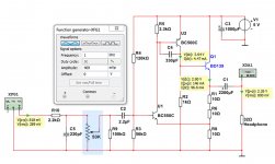
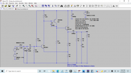
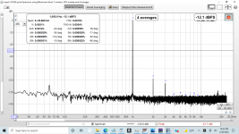
Today I breadboarded a 1.25x gain, lower-bias version shown in the attached schematic. Each channel uses four 1/2W 33-Ohm resistors that carry about 73 mA of bias current; they are warm but not hot. The attached measurements were collected using REW with a Scarlett Solo, driving 1V peak into a 33 Ohm resistor. By the way, I used 10 uF electrolytics on the input since I don't have any reasonable film capacitors right now, but otherwise the schematic is exactly what I built.
I think almost any BJTs will work with this classic topology, and anecdotally I tried a number of random combinations. The 2n3904/2n306/bd139 happened to have the lowest distortion, but that could easily be due samples I happened to have on hand and variations from measurement to measurement. The other channel is only slightly worse with a THD of 0.0016%, and is almost identical to an example I tried with bc549C/bc559C/bd139. The first version I built was 2n3904/2n3906/2n2222, which was about 3 dB worse, and the poorest example I tried was only 6-7 dB worse than the measurement posted here. The fact that performance does not significantly depend on the devices tells us that Lineup came up with a good and robust design!
The power supply I'm using is an old 12v DC 600mA wall-wart, and I was a little surprised that with a ~150 mA draw it is able to deliver over 15V so an LM317 could be used to clean it up.
For listening tests I used the Solo as the DAC, connected to my laptop playing lossless files. It definitely sounds as good as it measures.
I think I will solder up a version to keep at some point, although I will clean up a few things: get film input caps, replace the 5% carbon resistors sprinkled around, etc.
Does anyone have suggested improvements for a low-gain version?
Thanks Lineup!
Jason
Attachments
Last edited:

Thanks - I will move it and see if anything changes. I suspect you are correct that the Zobel just isn't required. In LTSpice I didn't see the Zobel shifting the phase or gain margins or anything even with some capacitive loading, but I just placed it there for good luck I guess. I'm not sure I will include it in the final version.
Yeah - my primary headphones are both 32 Ohms and around 114-115 dB / V (Grado SR-80e, AKG K553 Pro). I usually listen at 75-80 dB and doubt I ever need more than 200 mV even when I turn it up, so I'm only really interested in buffers and low-gain amps. My next headphones will probably be the 150-Ohm HD560s which are nominally 110 dB/V, so a buffer will still be fine.
It is usually easy to make amps lower gain, but stability always worries me. I can do the checks in LTSPice I learned about from Bob Cordell's book,, but my USB scope doesn't have the bandwidth to guarantee I will see instabilities. It is nominally a 10 MHz scope sampled at 100 MHz. I've tested it with a good source and found it has reasonable response up to 40 MHz and non-zero response up to ~70 MHz (with aliased signals of course), but I always feel like I'm a little in the dark.
I also recently played with a low-gain version of the REAL JLH headphone amp, but I like yours better.
jason
- Home
- Amplifiers
- Headphone Systems
- 3 Transistor HP Amplifier with low dist