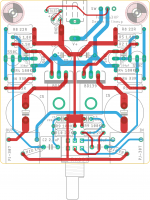
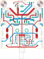
Looks pretty good -- admirably compact!
But I'd recommend more space around R1, R6, and R8. They dissipate quite a bit of heat -- shouldn't be against the BC550's or C5. If you don't want to give them more space radially, at least stagger them (offset them parallel to their long axis) so that the heat is less concentrated.
Also, top-side foil to electrolytics, jacks, and other flush-mounted parts can make for assembly/repair headaches. Not always possible to avoid, but often worth a few moments of extra effort.
Cheers
Looks pretty good -- admirably compact!
But I'd recommend more space around R1, R6, and R8. They dissipate quite a bit of heat -- shouldn't be against the BC550's or C5. If you don't want to give them more space radially, at least stagger them (offset them parallel to their long axis) so that the heat is less concentrated.
Also, top-side foil to electrolytics, jacks, and other flush-mounted parts can make for assembly/repair headaches. Not always possible to avoid, but often worth a few moments of extra effort.
Cheers
Rick, thank you very much for your comments..
Changed the placement quite a bit and BCs and BD139 are much closer to each other now.. Can't give more space to power resistors, mounting R1 on the bottom side is also an option too.
On another headamp thread, I was adviced from Hugh of Aspen for using polymer caps for the outputs, so reserved some place to experiment..
Attachments

while it seemed like there was no free space, surprisingly, more and more space appeared as played.
thank you all, your valuable comments much appreciated..
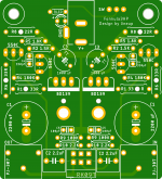
tried to follow your advices especially on power resistors placement.
thank you all, your valuable comments much appreciated..
tried to follow your advices especially on power resistors placement.
Attachments
Watch the component overlap of RH BC560 with C4 and R9,R10.
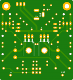
thank you avtech23,
tried to place those components without overlapping.
also added some holes to increase air flow for power resistors, i'm not sure if it helps 🙂
attached gerber file for those who wants to build this layout..
cheers..
Attachments

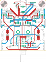
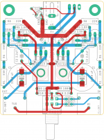
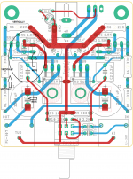
Yes! This is MUCH better. Well done! 😀
The only thing I noticed was that the center-trunk ground trace could be wider - with little penalty.
If I understand right -- the BD139's are UNDER the foil side, with their legs bent up to poke through the board? Then maybe there's room for the R3's ON TOP, over the space the OP's occupy underneath. That would give a > 2:1 improvement in EMI susceptibility due to the smaller loop containing the 1st stage bias supply.
Just my 2¢ ..
Cheers
Yes! This is MUCH better. Well done! 😀
The only thing I noticed was that the center-trunk ground trace could be wider - with little penalty.
If I understand right -- the BD139's are UNDER the foil side, with their legs bent up to poke through the board? Then maybe there's room for the R3's ON TOP, over the space the OP's occupy underneath. That would give a > 2:1 improvement in EMI susceptibility due to the smaller loop containing the 1st stage bias supply.
Just my 2¢ ..
Cheers
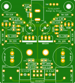
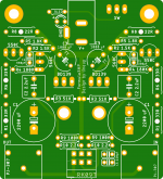
Rick, your comments helping me a lot, thank you so much..
yes, BD139's are on the bottom side and will be sandwiched by the pcb and heatsink.
moved the R3 together with the input cap, signal traces are much shorter now.
also C5s repositioned before the pot.
some components on the edge of overlapping but i hope there will be no problem..
may i ask what is the minimum voltage rating for output caps with 12V power supply? does it really see 12V? i tend to use a 16V cap but it will be hard to find a 2200uF in diameter of 13mm.
cheers..
Attachments

Last edited:
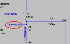
The capacitor sees about 9v difference:
so i can use a 10V cap within safety limits..
avtech23, thank you so much!
Most 2200uF / 16V are 12.5-13mm in diameter.
Set the output capacitor to the minimum supply voltage of the amplifier.
Set the output capacitor to the minimum supply voltage of the amplifier.
Most 2200uF / 16V are 12.5-13mm in diameter.
Set the output capacitor to the minimum supply voltage of the amplifier.
thank you knauf1919,
that is the rule i always follow but,
i had checked Nichicon FG and KZ series (2200uF 16V); both 16mm and Elnas (silmic and cerafine) are even larger.
going to look alternatives though..
You might be able to squeeze a little more room for bigger caps.
I use Wima MKS2 2.2uF caps for the input and they are 13 x 7.2 x 7.2mm case, which might free up a little space.
I use Wima MKS2 2.2uF caps for the input and they are 13 x 7.2 x 7.2mm case, which might free up a little space.
You might be able to squeeze a little more room for bigger caps.
I use Wima MKS2 2.2uF caps for the input and they are 13 x 7.2 x 7.2mm case, which might free up a little space.
it's already smaller than that; 7.2x7.2mm in wxd
used on the pcb what i have on hand is MKP4 series 4.7 uF, the smallest high capacity as of i know..
What software do you use to design your pcb?
it's Eagle 9.6.2 free version.
it's already smaller than that; 7.2x7.2mm in wxd
used on the pcb what i have on hand is MKP4 series 4.7 uF, the smallest high capacity as of i know..
Ah I see, it's hard to get a sense of scale sometimes!
Congratulation to your project, endia.
I am sure this headphone amplifier will sound good.
🙂
lineup, thank you so much!
your contribution to diy community invaluable.
i too sure it will sound good, can't wait to listen..
- Home
- Amplifiers
- Headphone Systems
- 3 Transistor HP Amplifier with low dist