Thanks, but there’s still a ways to go, Eric. I may reach the point of powering it up to tomorrow.
Hi, EricHi Marc
Does it create a surge when you apply the power..? After all it’s 3 x (SMPS + amps) all in parallel.
VERY nice work 👍
Thanks
Eric
Thanks for raising this question, I think there is worry about the surge with multi-boards parallel.
This PSU circuit integrated the PFC circuit inside, and you'll notice there is no large capacitor reservoir after the main rectifier..
Thanks,Eric

Thanks Von for sharing your details.Thanks, but there’s still a ways to go, Eric. I may reach the point of powering it up to tomorrow.
And, I think that's why I release an upgraded version of the I/O board,
Sorry for keeping you guys (I mean the first-batch owners) in-convenient.🤣
Thanks,Eric
Hello Friends,
You'll soon own this I/O buffer for the FFA amp module, let's make a poll here, which one do you need, RCA or XLR? I thank you for your kind input.
And, we may sell the "TypeC to RCA" and "Lighting to RCA" cables too, if you need.

Thanks,Eric
You'll soon own this I/O buffer for the FFA amp module, let's make a poll here, which one do you need, RCA or XLR? I thank you for your kind input.
And, we may sell the "TypeC to RCA" and "Lighting to RCA" cables too, if you need.
Thanks,Eric
Looking good, Eric, your response time is amazing. Only question, why is the switch in the middle of the input connectors? I hope you do not mind honest criticism, I, for one, would have to reach a finger in there between the "Y" end of the RCA cable pair to turn it on. Now don't get me wrong, them gyals go loud with my finger
In my case, I don't want a rear mounted switch, so doesn't really make a difference. My I make a recommendation, consider the merit of the switch being fitted to a JST or similar with a bit of ribbon for front or rear insertion
In my case, I don't want a rear mounted switch, so doesn't really make a difference. My I make a recommendation, consider the merit of the switch being fitted to a JST or similar with a bit of ribbon for front or rear insertion
I should have just waited and ordered RCA boards. 😀
Nevertheless, I will continue with my build.
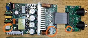
Eric (or others who can readily tell), can you provide specifications for the three connectors highlighted in the attached picture (i.e., connector/pin/terminal type and pitch)?
I want to minimize ordering the wrong things. I’d rather not solder to these pins and want to be able to easily disconnect the fan(s).
Nevertheless, I will continue with my build.
Eric (or others who can readily tell), can you provide specifications for the three connectors highlighted in the attached picture (i.e., connector/pin/terminal type and pitch)?
I want to minimize ordering the wrong things. I’d rather not solder to these pins and want to be able to easily disconnect the fan(s).
Attachments
Eric,
I may go with both and make the rear panel removable on my case so I can change if I want (I will be purchasing FFA003 modules). I will probably unsolder switch and mount mine on front of case.
Bill
I may go with both and make the rear panel removable on my case so I can change if I want (I will be purchasing FFA003 modules). I will probably unsolder switch and mount mine on front of case.
Bill
Last edited:
Hi, RandyLooking good, Eric, your response time is amazing. Only question, why is the switch in the middle of the input connectors? I hope you do not mind honest criticism, I, for one, would have to reach a finger in there between the "Y" end of the RCA cable pair to turn it on. Now don't get me wrong, them gyals go loud with my finger
In my case, I don't want a rear mounted switch, so doesn't really make a difference. My I make a recommendation, consider the merit of the switch being fitted to a JST or similar with a bit of ribbon for front or rear insertion
Your comments are always welcome. I appreciate your inputs.
Put the toggle switch between the two input jacks, that's my design philosophy with symmetrical looking for the rear panel 😀 laughing here.
And, with the field experiment, the toggle SW will not interfere with input cables.
But, your suggestion is excellent, put the JST or similar wafer parallel with this SW, and DIYer can route it in the front panel.
Thanks,Eric
Personally, I can support this requirement, just let me know which type of input connectors you need to pcaked~~~Personally I would prefer if the IO board to come without RCA or XLR connectors installed.
Thanks, Eric
Hi, VonI should have just waited and ordered RCA boards. 😀
Nevertheless, I will continue with my build.
Eric (or others who can readily tell), can you provide specifications for the three connectors highlighted in the attached picture (i.e., connector/pin/terminal type and pitch)?
I want to minimize ordering the wrong things. I’d rather not solder to these pins and want to be able to easily disconnect the fan(s).
If you need it, the I/O buffers are all free for you, only need the shipping charging,
Try to google the "VH3.96 -4Y" for the amp output connector, it's 4pin,3.96mm pitch wafer. I also can provide you the mating cables for this wafer, sorry for missing them in your delivery.
Thanks,Eric
Hi, FriendWhen will be available the next batch with the pre-amp board and what will be the price?
We'll announce it to this forum next week, and welcome to try it. And the price is no change as mentioned on the first page($49.9 w/o shipping).
Thanks,Eric
Hi, BillEric,
I may go with both and make the rear panel removable on my case so I can change if I want (I will be purchasing FFA003 modules). I will probably unsolder switch and mount mine on front of case.
Bill
Thanks for your continuous support.
Like Randy's suggestion, I'll parallel the wafer with this toggle switch to let it easily re-wired to front panel at FFA003 IO buffer.
Thanks,Eric
Eric,
Thanks for your ongoing support, I have been enjoying this amp on my work bench so much I had to upgrade my Dac. I had been using a 15 watt class A amp and was happy but the head room was such a noticeable improvement I had to keep it on my test bench .
thanks for offering these to the diy community
Bill
Thanks, Eric. I’ll PM you about the buffers, etc.Hi, Von
If you need it, the I/O buffers are all free for you, only need the shipping charging,
Try to google the "VH3.96 -4Y" for the amp output connector, it's 4pin,3.96mm pitch wafer. I also can provide you the mating cables for this wafer, sorry for missing them in your delivery.
Thanks,Eric
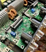
I discovered that I have two pin terminal blocks that will fit in the area marked “Fan,” so that has been solved.
Attachments
Hi, Randy
Your comments are always welcome. I appreciate your inputs.
Put the toggle switch between the two input jacks, that's my design philosophy with symmetrical looking for the rear panel 😀 laughing here.
And, with the field experiment, the toggle SW will not interfere with input cables.
But, your suggestion is excellent, put the JST or similar wafer parallel with this SW, and DIYer can route it in the front panel.
Thanks,Eric
Hi, Bill
Thanks for your continuous support.
Like Randy's suggestion, I'll parallel the wafer with this toggle switch to let it easily re-wired to front panel at FFA003 IO buffer.
Thanks,Eric
Awesome. I think the FFA003 will be a big seller. When you are ready to do so, please tell me more about the "heavy duty" philosophy. I like the sounds of that
I still can't find a push button style switch to replace the current one with, as I don't know which types of push button switches can be made to work here. My limitations are pure cosmetic, so looking for gold tones but no silver ones
- Home
- Vendor's Bazaar
- 2x150W Amp module for sale