Dear Ladislav,
thx for your detailed report!
And yes I like the performance of SA2014 too (many thanks to all who helped to design this amp!) since the first day. My SA2014 quad channel amp now has played more as 6 thousands of hours and mastered every type of sound and it is still a pleasure every day to listen sound using this amp.
I agree everbody needs to build this beast!😀
If the treble at high volume isn't clear: the input impedance of SA2014 is relatively low. Your preamp hopefully has a 600R output...
BR, Toni
Last edited:
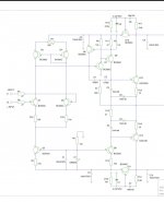
I did my own board for mydoa 3.1 and it doesnt work properly. I lowered r8 and r6 values for lower voltage rails (15v) and r5 is 700ohm for mje243 253 output transistors. All other transistors bc327 337
The ccs led doesnt turn on and i get 13v offset (unadjustable)
If i substitute 47k resistor for the input stage ccs i can get 100mv offset and it plays music, but with very distorted bass. The ccs led still doesnt turn on.
Since it plays music can i assume the pcb design is correct and that the component value/choices are the issue?
How should i troubleshoot this?
Attached is a pic of my board.
Attachments

Dear Donovas,
to which schematic do you refer? Changing the TMC compensation capacitors and at the same time changing all transistor types from the recommended ones needs more or less a redesign of the schematic and part values.
Distorted bass can also be a problem of too low output impedance and/or of course also oscillation.
The GREEN led should be a Lite-on LTL1CHKGKNN or another LED with similar specs. This LED type should show a weak glow. If you use a very old standard green LED the CCS my not even work correctly.
MyDOA with original parts works with +/-10V up to +/-24V without any problems.
BR, Toni
Thank you for the detailed answer Toni.Dear Donovas,
to which schematic do you refer? Changing the TMC compensation capacitors and at the same time changing all transistor types from the recommended ones needs more or less a redesign of the schematic and part values.
Distorted bass can also be a problem of too low output impedance and/or of course also oscillation.
The GREEN led should be a Lite-on LTL1CHKGKNN or another LED with similar specs. This LED type should show a weak glow. If you use a very old standard green LED the CCS my not even work correctly.
MyDOA with original parts works with +/-10V up to +/-24V without any problems.
BR, Toni
Unfortunately i will have to abandon this board since my goal was to find a project to use up my generic components.
Could i ask you why only the specific led could work with your ccs? I never heard of needing a specific brand of led for its parameters
Dear Donovas,
I ask again: to which schematic do you refer?
LED type x' forward voltage isn't the same as LED type y.
To reuse your parts using my schematic is possible, but you have to recalculate many part values. Show your usage szenario including external components.
BR, Toni
I ask again: to which schematic do you refer?
LED type x' forward voltage isn't the same as LED type y.
To reuse your parts using my schematic is possible, but you have to recalculate many part values. Show your usage szenario including external components.
BR, Toni
Attachments

You could use the SMD equivalents BC850C and BC860C available in SOT23 case. Using SOT23 to TO92 adapter PCBs would help.
I have a huge stock of hard to get parts for all of my projects. Just PM me, if you need some..
BR, Toni
I have a huge stock of hard to get parts for all of my projects. Just PM me, if you need some..
BR, Toni
ASTXlabs still alive
A little bit off topic: I'm focused on developing an analog preamplifier digitally controlled for SA20XX amplifier series.
Currently I'm soldering a first prototype using optoMOS switches.
Volume can be controlled from -63.5 dB to + 12dB in 0.5 dB steps.
If this project fails due to bad THD values the next step is to use a discrete JFET volume control or a PGA2320 based volume controller.
Have fun, Toni
Every active device uses silicon to amplify. If you know details and measurements of a failed reference project using optoMOS devices, please let us know this.
BTW: Your comment disqualifies every MOSFET based loudspeaker relay. 😉
BR, Toni
BTW: Your comment disqualifies every MOSFET based loudspeaker relay. 😉
BR, Toni
I don't see a BJT or FET solution that beats a gold contact relay attenuator in terms of THD.
That wasn't the challenge to develop another relay based attenuator. This one uses fast switching optoMOS where volume switching during zero cross can be realized. DOT
Last edited:
Hi tony
Nice to see you are at a new development
At one time I made and tested a few pga or volume controller designs, using max9729 and pga2320 types. I found that the gain structure in the 9729 having 32 steps was good, you do need mute and a few steps below -64dB imo
Steps of 0.5 dB are not necessary also. You will find out in testing
What controller are you using and what dev platform
I was also looking at the muse parts, higher performers in specs over the older TI pga parts
Sometimes a bass boost is a minimum feature to have instead of tone controls
o PIC18F46K22
o several MCP23S17
o sdcc compiler
o Home brew software
o Inputs have manually adjustable gain -15/+14dB using hex encoders reachable from back panel
o balanced interconnects
o d.self tone control bass/treble with adjustable base frequency and "direct/bypass switch". using 24 position dual/stereo switches with 5k total linear resistor value for low noise
o self developed remote control using nec protocol
o 8 inputs.
o 4*20 oled white display with configurable brightness
o 2 rotary encoders for inputs/monitor mix selection and volume control and setup.
... I dislike the relay "clicks" ...I don't see a BJT or FET solution that beats a gold contact relay attenuator in terms of THD.
- Home
- Amplifiers
- Solid State
- 2stageEF high performance class AB power amp / 200W8R / 400W4R