Last edited:

Dear Asuslover,
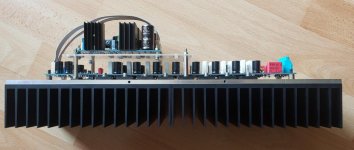
I was trying to make the smallest managable dimensions. My limitation due to my hifi shelf are 48cm wide and 40cm deep at max. Another limits are heatsinks. I decided for two pieces of K 190 heatsinks per channel. They are 190mm wide, so I concluded that the spreader is 381 mm long. (1mm is reserve, because I am not mechanicaly perfect). The heatsinks you could find/buy from the company Gamaaluminium. The catalogue is at the link Hlinikove chladiče | GAMAaluminium - the catalogue is in English, too.
I did not make holes manually. I ordered the all the alluminium parts from Customized front-panels, electronics panels, face panels, device panels, front-plates, anodized panels, aluminium panels
They are professional maker of front pannels for Hifi devices at reasonable prices. They provide simple CAD software where you can design your pannel and then they produce it. I can share the design of spreader if somebody would be interested. (The price for 2 pieces of spreaders 6mm thick is 53 Euro plus postage.)
Ladislav
What's sad is that you don't get a large heat sink in one piece.
I think the heat is spreaded very well in this case. So I dont see any difficulties with two pieces.
🙂
I have ordered always as private person - no problem so far.Corporate customers only.
I think the heat is spreaded very well in this case. So I dont see any difficulties with two pieces.
🙂
The K190 has 0,47 °C/W if 150mm high. Think you have about > 120mm heigth?
2 of them with heat spreader may get down to 0.25 -0.30 °C/W
Idle dissipation is about 60W per channel. This gives about 18 degree above ambient. May not need active cooling. OK - depends on your room temperature and use case.
For example my 4 channel SA2014:
A 210mm high ct-540 has ~ 0.15 °C/W. I have mounted 2 channel on one of this heatsinks. Total dissipation in this case is 120W per heatsink. gives nearly the same temperature above ambient like the double K190 with heat spreader!
Well done!
NICE WORK!!!
That is very nice looking! KUDOS!
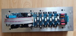
All pcb's are now ready for mounting and cabling.
The case needs some work (drilling and engraving) and maybe the first prototype amplifier will be ready in the next 2 - 3 weeks for extended real life audio tests.
That is very nice looking! KUDOS!
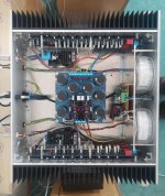
SA2014 modules wired. At this moment still without loudspeaker protection. Everything is working, idle current set to 21mV/0,47 ohm (44 mA per device) at cold heatsink.
Iddle current is decreasing with higher temperature. It drops to 15mV/0,47 ohm (32 mA) when stabil heatsink temperature is achieved.
Output offset is measured about 4-7 mV.
I am looking forward to listening experience.
Ladislav
Iddle current is decreasing with higher temperature. It drops to 15mV/0,47 ohm (32 mA) when stabil heatsink temperature is achieved.
Output offset is measured about 4-7 mV.
I am looking forward to listening experience.
Ladislav
Attachments
Nice setup!
Regarding offset voltage: have you wired the output negative pole to input negative pole?
And if the idle temperature has settled up you can increase the bias level to fit the 42mV between TP1 and TP3 for lowest THD.
BR, Toni
Regarding offset voltage: have you wired the output negative pole to input negative pole?
And if the idle temperature has settled up you can increase the bias level to fit the 42mV between TP1 and TP3 for lowest THD.
BR, Toni
Dear Toni,
I am not sure I understand what you mean by output negative pole. There is speaker connector and the GND. Both of them are connected. In the input there is 10 pins connector so I hope that it is not mismatched.
BR, Ladislav
I am not sure I understand what you mean by output negative pole. There is speaker connector and the GND. Both of them are connected. In the input there is 10 pins connector so I hope that it is not mismatched.
BR, Ladislav
SA2014 modules wired. At this moment still without loudspeaker protection. Everything is working, idle current set to 21mV/0,47 ohm (44 mA per device) at cold heatsink.
Iddle current is decreasing with higher temperature. It drops to 15mV/0,47 ohm (32 mA) when stabil heatsink temperature is achieved.
Output offset is measured about 4-7 mV.
I am looking forward to listening experience.
Ladislav
it seems your toroids will have a shorted turn via the center bolt , please check .
The IPS and the OPS grounds are only connected via a 10R resistor to keep the input ground clean. The IPS input ground pin need to be connected to speaker output ground. This wire should be routed as far away from toroids as possible.Dear Toni,
I am not sure I understand what you mean by output negative pole. There is speaker connector and the GND. Both of them are connected. In the input there is 10 pins connector so I hope that it is not mismatched.
BR, Ladislav
- Home
- Amplifiers
- Solid State
- 2stageEF high performance class AB power amp / 200W8R / 400W4R