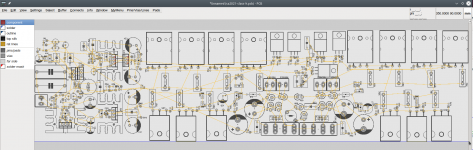
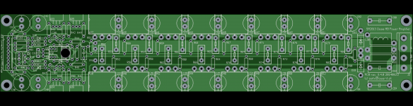
SA2021 New Class H Powerhorse - PCB design 2
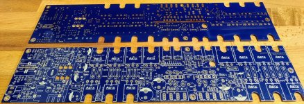
Some progress...
There will be a VI limiter connector which can be optional populated using a small pcb.
Alternatively there will be another socket to be populated with a small pcb using hall sensors to control currents and calculate SOA using microcontrollers.
Have fun,
Toni
Some progress...
There will be a VI limiter connector which can be optional populated using a small pcb.
Alternatively there will be another socket to be populated with a small pcb using hall sensors to control currents and calculate SOA using microcontrollers.
Have fun,
Toni
Attachments
I need a 400W amp for my Maggies. Are the gerbers good to go for this amp in 979 and 980?? anyone know if it is a stable design and sounds good?
Dear Freecrowder,
the amp has been built many times also by other users. Mine (4 channel version) runs every day since the built has been finished during 2013/2014. The amp has no "own sound". It simply reproduces the input signal without hearable distortions full range with THD in low dual digit ppm till full power. Due to the total bias of about 500mA you get the first watts in pure class A.
The pcb layout has been updated with new silk screen (have some on stock; also hard to get parts like 2SC4793...) but of course you can use the gerbers. They are error free.
BR, Toni
Can someone explain this to me? Can PWM amplifiers have the same excellent measured values as normal linear amplifiers?
I need a 400W amp for my Maggies. Are the gerbers good to go for this amp in 979 and 980?? anyone know if it is a stable design and sounds good?
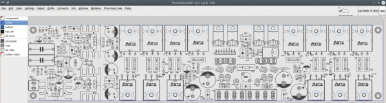
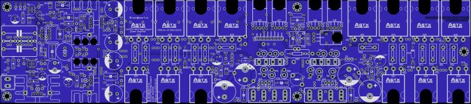
There are only minor differences - mostly silkscreen. The only real difference is where you can mount alternative input MKPs:
BR, Toni
P.S.: The blue ones are on stock
Attachments

Thank you ASTX. I'm deciding now on what amp I want to build next. The fact you have boards helps tremendously. Do you have pricing? is shipping to USA very expensive.
So (so far) similar performance to SA2014 but a lot less heat dissipation? (excuse my newbie question)
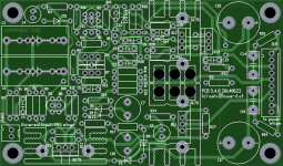
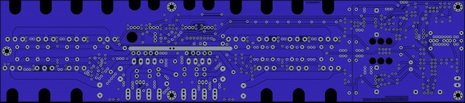
What are the dimensions of that PCB?
What are the dimensions of that PCB?
Dear Steve,
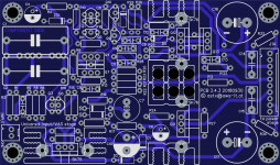
it has similar performance as SA2014. Of course a little bit higher distortion during transition from lower to upper rail voltages but still very low. Here we are talking of 0.005% THD 20kHz at around 15W@8R. The first watts are of nearly same performance as SA2014. The NCH design allows higher output power at lower "standby" dissipation with very high performance and total 8R power > 300-400W@8R.
Size is 340x75 mm
BR, Toni
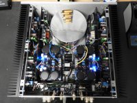
... project successfully finished!
I keep looking at this pic. Incredible work.
How much room is there between the rear fascia and the inner soft iron shielding? Were I to build this I would have to fit my Self's Balanced to Single_Ended Input boards in that gap. It doesn't look like they'd fit and would mean an even deeper enclosure.
PS: where did you put thee star ground and what's the little PSU looking board to the left of the toroid?
Attachments
Last edited:
Many thanks!... Incredible work.
Above the backpanel pcb there are the 4 RCA inputs mounted. Maybe there is the needed space. I can check the next days if your RCA/Balanced input fits there.How much room is there between the rear fascia and the inner soft iron shielding? Were I to build this I would have to fit my Self's Balanced to Single_Ended Input boards in that gap. It doesn't look like they'd fit and would mean an even deeper enclosure.
The star ground is on the backpanel pcb directly in the middle under the 4 RCAs (several white 6.3mm socket housings are there viewable). And yes, it's the 12V AC supply for the backpanel parts (relais power; MCP2221 power)PS: where did you put thee star ground and what's the little PSU looking board to the left of the toroid?
Have fun, Toni
Last edited:
Hi, Toni
SA2015 V-MOSFET (3pairs) look interesting. Can I use smd resistors instead of vertical TH resistors (Are the space in pcb suitable for smd?) Can I use to126 tr instead of bc550 for q15 ? So that it can be bolted down to the heatsink.
SA2015 V-MOSFET (3pairs) look interesting. Can I use smd resistors instead of vertical TH resistors (Are the space in pcb suitable for smd?) Can I use to126 tr instead of bc550 for q15 ? So that it can be bolted down to the heatsink.
Last edited:
Dear chat72,
theoretically some th resistors can be replaced by a 1206 SMD resistor but the smd resistors do not have the same maximum power dissipation of a metal film "th" resistors ("th" typical max. 600mW vs smd max. 250mW) and may fail.
At least R23, R24, R25, R29, R30, R43, R44, R46, R47, R61, R80, R81 should be through hole metal film 0.6W (part numbers from schematic post # 1409). If using SMD resistors please use only thin film parts!
The BC550C as bias Transistor as well as the red LED is mandatory for stable bias from cold to hot.
A mounting detail is shown here in post 1422 and here in post 1557.
Diyaudio member Thimios has build the SA2015 too - see his detail info using this thread index in post #1.
Bend the BC550C legs so that the flat side is parallel with the heatsink (a small amount of thermal paste helps a lot). The red led only needs to be in the middle between heatsink and pcb - no thermal paste needed.
BR, Toni
P.S.: "unfortunately" some pcb's are on stock...
Last edited:

- Home
- Amplifiers
- Solid State
- 2stageEF high performance class AB power amp / 200W8R / 400W4R