sa2015
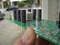
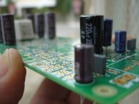
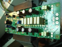
A new travel began🙂
No solder anything yet,just try to see what i have on hand now......many missing parts ,some other not what exactly recommended🙁
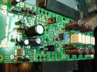
A new travel began🙂
No solder anything yet,just try to see what i have on hand now......many missing parts ,some other not what exactly recommended🙁
Attachments
Last edited:
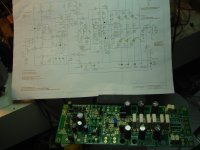
Cool! Have a look at your PM!A new travel began🙂
No solder anything yet,just try to see what i have on hand now......many missing parts ,some other not what exactly recommended🙁
BR, Toni
This great job belongs to astx,i'm a repeater only..great Job!!! thx for the pictures.
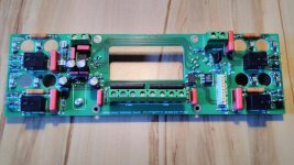
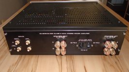
4 channel back panel ... sorry for the bad picture quality - better images will follow. Very similar to the 4 channel back panel which I designed for my class d amplifier...This is the back panel electronics including speaker relais for the 4 channel MOSFET power amplifier...
...
Attachments
This is my best guess as to proper modeling accounting to thermal drift. It will still be more accurate than the previous models, even if it makes me feel dirty.
Thoughts?
Do you still need more datapoints for FC and Onsemi BC5x0C?
BTW: I have 2 different lots of 2k pcs Fairchild BC5x0C:
- BC550C datecode 1224 have hFe ~600
- BC560C datecode 1224 have hFe ~600
- BC550C datecode 1549 have hFe ~420
- BC560C datecode 1605 have hFe ~420
BR, Toni
Can you run some more tests of different date codes so we can see how parameters vary? Just do the same test as last time.
I can use the data given so far. More transistors would also be good, for instance BC3x7-40, 2N5551, KSA992, etc. so I can add quasi-saturation, as well as know the manufacturer and approximate date.
I can use the data given so far. More transistors would also be good, for instance BC3x7-40, 2N5551, KSA992, etc. so I can add quasi-saturation, as well as know the manufacturer and approximate date.
Can you run some more tests of different date codes so we can see how parameters vary? Just do the same test as last time.
I can use the data given so far. More transistors would also be good, for instance BC3x7-40, 2N5551, KSA992, etc. so I can add quasi-saturation, as well as know the manufacturer and approximate date.
Yes additional measurements are possible but will take some days.
Are you sure the DCA75pro measurements are accurate enough to readjust the simulation models? Can you see any temperature effects if the measurement stepping increases Ib and therefore Ic (and indirectly increases device temperature)?
BR, Toni
I think the thermal drift is minimal and the models can be fitted within 20% this way. Do you know which direction in time the cures are traced?
The curve trace for about 50 datapoints and 5 curves takes about 1minute.I think the thermal drift is minimal and the models can be fitted within 20% this way. Do you know which direction in time the cures are traced?
I can trace the duration time of one sample using my digital scope to get a better feeling of possible device heating...
BR, Toni
Does it sweep voltage upwards or downwards, and does it start at the low Ib step and step up, or does it start at the high Ib and step down?
Can you also include Vbe with the Vce sweeps? This might give a usable indicator of junction temperature.
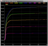
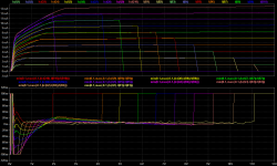
250 data points in 1 minute means about 240mS testing period. Based on the Siemens thermal response data, after 3 datapoints or so the thermal drift should be mostly over. This means that if I draw a constant power curve on the VI plane, the intersections of it with Ic should be very close in temperature. Based on this information I've estimated the model fit differently this time.
The bottom graph shows the model error as a fraction of Ic. So even with thermal drift, the model can match the data to 2% from 0.5V and up. Much closer at the equal temperature points.
The model seems to suggest that there is a 10mV or so DC offset in the data. The data itself shows about 3mV at Ic=0, but 10mV helps the model fit for some reason.
Attachments
250 data points in 1 minute means about 240mS testing period....
Just checked with scope: DCA75pro seems to take every 10ms one sample with a test duration of about 2 - 5 µs. A 250 sample test cycle (50 samples per trace , 5 traces) takes about 34 seconds. A 1000 samples (100 samples per trace, 10 traces) test cycle takes about 105 seconds. Sampling stops if Ic is 12mA.
Due to the very short measurement time and the relatively long cooling time the device temperature changes should be minimized.
The sampling starts with low Vce and highest Ib and ends with highest Vce and lowest Ib. The traces are stepped using constant Ib current. The lowest Ib current which can be selected is 4 µA.
Unfortunately the measurement device is unable to measure Vbe during Ic/Vce sweep.
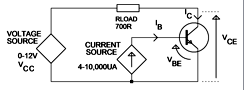
Also have a look at the DCA75pro internal test circuit. Should I continue to fetch data?
BR, Toni
Attachments
5uS should mean thermal drift is insignificant. So it looks like I can just fit these curves directly. Go a head and try some other transistors.
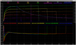
Small signal bjt measurement data 1
... some measurement data to play with...
Can't go below 4µA Ib.
Higher hFe transistors have traces with 4 - 40µA sweep
Lower hFe transistors have traces with 7 - 70µA sweep
BR, Toni
... some measurement data to play with...
Can't go below 4µA Ib.
Higher hFe transistors have traces with 4 - 40µA sweep
Lower hFe transistors have traces with 7 - 70µA sweep
BR, Toni
Code:
FC-BC550C hFe=580 datecode/lot=1224
NPN Silicon BJT
Red-C Green-B Blue-E
hFE=580 at Ic=5,00mA
Vbe=0,763V at Ib=5,00mA
VceSat=0,022V at Ic=5,0mA and Ib=1,00mA
IcLeak=0.000mA

FC-BC550C hFe=450 datecode/lot=1605
NPN Silicon BJT
Red-C Green-B Blue-E
hFE=452 at Ic=5,00mA
Vbe=0,764V at Ib=5,00mA
VceSat=0,023V at Ic=5,0mA and Ib=1,01mA
IcLeak=0.000mA

FC-BC560C hFe=570 datecode/lot=1225
PNP Silicon BJT
Red-C Green-B Blue-E
hFE=572 at Ic=5,00mA
Vbe=0,770V at Ib=5,00mA
VceSat=0,031V at Ic=5,0mA and Ib=1,00mA
IcLeak=0.000mA

FC-BC560C hFe=460 datecode/lot=1549
PNP Silicon BJT
Red-C Green-B Blue-E
hFE=460 at Ic=5,00mA
Vbe=0,770V at Ib=5,00mA
VceSat=0,026V at Ic=5,0mA and Ib=1,00mA
IcLeak=0.000mA


FC-BC33740 hFe=436 datecode/lot=1230
NPN Silicon BJT
Red-C Green-B Blue-E
hFE=436 at Ic=4,99mA
Vbe=0,753V at Ib=5,00mA
VceSat=0,005V at Ic=5,0mA and Ib=1,00mA
IcLeak=0.000mA

FC-BC32740 hFe=560 datecode/lot=1229
PNP Silicon BJT
Red-C Green-B Blue-E
hFE=560 at Ic=5,02mA
Vbe=0,743V at Ib=5,00mA
VceSat=0,009V at Ic=5,0mA and Ib=1,00mA
IcLeak=0.000mA

FC-KSC1815YC hFe=190 datecode/lot=1245
NPN Silicon BJT
Red-E Green-C Blue-B
hFE=187 at Ic=5,01mA
Vbe=0,765V at Ib=5,00mA
VceSat=0,026V at Ic=5,0mA and Ib=1,01mA
IcLeak=0.000mA

FC-KSA1015GR hFe=290 datecode/lot=1241
PNP Silicon BJT
Red-E Green-C Blue-B
hFE=291 at Ic=5,00mA
Vbe=0,771V at Ib=5,01mA
VceSat=0,032V at Ic=5,0mA and Ib=1,00mA
IcLeak=0.000mA

FC-KSC1845FTA hFe=330 datecode/lot=1243
NPN Silicon BJT
Red-E Green-C Blue-B
hFE=332 at Ic=4,99mA
Vbe=0,757V at Ib=5,00mA
VceSat=0,034V at Ic=5,0mA and Ib=1,00mA
IcLeak=0.000mA

FC-KSA992FTA hFe=380 datecode/lot=1314
PNP Silicon BJT
Red-E Green-C Blue-B
hFE=380 at Ic=5,01mA
Vbe=0,765V at Ib=5,00mA
VceSat=0,040V at Ic=5,0mA and Ib=1,00mA
IcLeak=0.000mA

ON-BC550C hFe=580 datecode/lot=1007
NPN Silicon BJT
Red-C Green-B Blue-E
hFE=578 at Ic=4,99mA
Vbe=0,792V at Ib=5,00mA
VceSat=0,026V at Ic=5,0mA and Ib=1,00mA
IcLeak=0.000mA

ON-BC560C hFe=540 datecode/lot=1108
PNP Silicon BJT
Red-C Green-B Blue-E
hFE=539 at Ic=4,99mA
Vbe=0,787V at Ib=5,00mA
VceSat=0,030V at Ic=5,0mA and Ib=1,00mA
IcLeak=0.000mA

ON-MPSA18 hFe=960 datecode/lot=1205
NPN Silicon BJT
Red-E Green-B Blue-C
hFE=959 at Ic=5,01mA
Vbe=0,792V at Ib=5,00mA
VceSat=0,024V at Ic=5,0mA and Ib=1,00mA
IcLeak=0.000mA
Attachments
- Home
- Amplifiers
- Solid State
- 2stageEF high performance class AB power amp / 200W8R / 400W4R