Very nice!!! 🙂A package just arrived and here is what was on the top layer... 😀
I thought so too until I took a closer look today. They didn't bead finish all the lettering like they were meant to. Three projects, three enclosures from Modu and three times now things have had to go back to them...unbelievable.
... that's bad news ... makes me sad ... 🙁I thought so too until I took a closer look today. They didn't bead finish all the lettering like they were meant to. Three projects, three enclosures from Modu and three times now things have had to go back to them...unbelievable.
Attachments make me happy ... 🙂
Hopefully now without any mask errors ...
Attachments
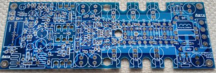
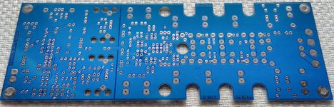
This is going to be a beast...
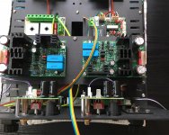
Second Modu mistake discovered. I always do my drawings/DWG as an internal view (looking down into the enclosure) and ask them to mirror them for drilling. Well they didn't. The pillar top right is set back a little - the problem is that it is the one on the left that's meant to be set back. This is because a small PCB for the front panel switch sits on the rear of the front plate right at this point meaning there is less room. Luckily there's still a couple of mm gap, but it means I have to mount the iron shelf upside down as well. So I have just been forced to swap the position of my star ground and main controller unit. 🙁
Second Modu mistake discovered. I always do my drawings/DWG as an internal view (looking down into the enclosure) and ask them to mirror them for drilling. Well they didn't. The pillar top right is set back a little - the problem is that it is the one on the left that's meant to be set back. This is because a small PCB for the front panel switch sits on the rear of the front plate right at this point meaning there is less room. Luckily there's still a couple of mm gap, but it means I have to mount the iron shelf upside down as well. So I have just been forced to swap the position of my star ground and main controller unit. 🙁
Attachments
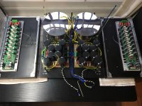
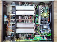
A few more quick iPhone pics as making some progress slowly. Back panel including my implementation of Self's balanced to single-ended input board (more info here) and OPS mounting on heat spreader and heat sink (including wiring to NTC for thermal monitoring).
Attachments
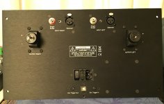
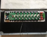
A few more quick iPhone pics as making some progress slowly. Back panel including my implementation of Self's balanced to single-ended input board (more info here) and OPS mounting on heat spreader and heat sink (including wiring to NTC for thermal monitoring).
Looks really impressive!

Never seen such binding posts for speakers. Maybe you can provide a link here?
And hopefully you can provide some higher resolution pictures too...
BR, Toni
Thanks! Still a lot to do but will be delayed by Modu. Here is a link to the Cardas binding posts
CPBP (Cardas Patended Binding Post)
They work really well
I will take better pictures when I am further along.
CPBP (Cardas Patended Binding Post)
They work really well
I will take better pictures when I am further along.
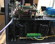
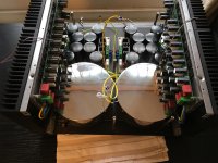
Slowly making some progress... Not a lot of spare room along the bottom or at the rear of the enclosure!
Attachments
Last edited:

SGK,
Love the exacting detail you implement in your builds. Exactly how it should be done...Kudos!
Astx,
Thanks for sharing the design. I don't have a need for a 200w amplifier at the moment (my requirements are served at 1/10th that power), I do appreciate a well thought out design.
Best,
Anand.
Love the exacting detail you implement in your builds. Exactly how it should be done...Kudos!
Astx,
Thanks for sharing the design. I don't have a need for a 200w amplifier at the moment (my requirements are served at 1/10th that power), I do appreciate a well thought out design.
Best,
Anand.
@astx I got there in the end (with enough huffing and puffing to blow a lot of piglet houses down and more cursing than I am proud of) I had to attach the top screw of the front plate and then slide it and the heatsinks forward to be able to get to the bottom screws. The challenge was I could then no longer reach the front heatsink mounting nuts. So before I moved everything I had to place a drop of UV setting adhesive around the nut and shakeproof washer and hope that it held enough for me to be able to screw them up from the bottom. Luckily it worked. Why Modu don't make these fittings with threads I don't know. It would make things so much easier. Now I need to redo the Aux PSUs mains wiring loom with my newly arrived much thinner (20AWG, 0.62mm^2) wire and drop in the iron shelf. Getting there...
@nycavsr2000 Thanks Anand. Hopefully it all works! Have a look at Toni's 50W build...
More to come 😀
@nycavsr2000 Thanks Anand. Hopefully it all works! Have a look at Toni's 50W build...
More to come 😀
Attachments
Last edited:
...
Thanks for sharing the design. I don't have a need for a 200w amplifier at the moment (my requirements are served at 1/10th that power), I do appreciate a well thought out design.
...
You are welcome! The design includes a lot of help of the diyaudio community too! Many thanks to all helpers!
BTW: the threads first page (post #1) contains an updated index with links to all sub projects, smaller amplifiers, housekeeping, discrete opamp ...
BR, Toni
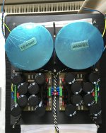
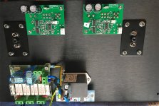
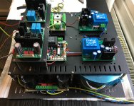
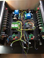
More progress. Shelf is made of iron (anodised) to help suppress any EMI/MR from PSUs below.
Aux PSUs at front. Toni's Star Ground and Main Controller Unit in middle. My output relay and Zobel boards at rear (foreground).
OPS sit on heat spreaders, in turn bolted to heat sinks. They sit in the upper half of the heat sink because of width constraints (not such a bad idea to keep them away from PSUs in lower deck. OPS output to output relay/Zobel board will be routed along top of iron shelf.
Hopefully my work will do Toni's justice!
Attachments
...
Hopefully my work will do Toni's justice!
Very nice! Awesome!
Maybe you want to add some more safety to your 230V cables like I have done here using "plastic braid sleeve":
http://www.diyaudio.com/forums/soli...s-ab-power-amp-200w8r-400w4r.html#post4767489 (right most picture)
E.g.: this one https://www.buerklin.com/en/search?text=canuflex
BR, Toni
Last edited:
Ugh. I have two mains runs: one to the MCU and one double run to the Aux PSUs. The former is easily accessed; the latter requires me to remove the shelf.
The safety aspect is just that the sleeve serves as a warning for high voltages? I can't see any other purpose as the wire itself is rated for high temp/abrasion etc.
I've not sleeved the toroid secondary runs or the +/-70V runs to the OPS. Doing that would require some significant dismantling and reassembly.
- Home
- Amplifiers
- Solid State
- 2stageEF high performance class AB power amp / 200W8R / 400W4R