
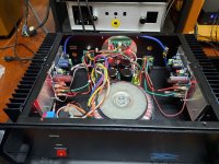
Both channels are singing now. Sound great so far, sound quite accurate. Bass a little bit overwhelming, but I have small room. I think position of speakers need adjusting.
I use 30vac, it is 40Vdc, 40000uf for both channels. Bias is 18mv across 0.12 Ohms.
Bias is stable but offset is a bit high. I have around -58mv (red probe is on speaker output) on both channels. I match hfe but not vbe. Is there anywhere I can adjust this without pull out transistors? Can it be done by adjusting r10 and r18?
Congratulations!
If the input ground and the speaker output ground is connected to the silent star ground, offset will be zero...
If the input ground and the speaker output ground is connected to the silent star ground, offset will be zero...
Hi Toni,
Having spent some time reading through the thread, I am hoping to construct a MOSFET version of your impressive amplifier. I tend to favour the Lateral MOSFET version E1) SA2016 L-MOSFET using approx 50V supply rails unless you feel that C1) SA2015 V-MOSFET offers any advantage in terms of performance or stability?
I would be grateful if you could let me know your view.
I have also sent you an email to sa2016 (at) aws-it.at enquiring about the availability of PCBs.
Thank you and best wishes
David
Thx for your interest in building one SA20xx amp.
I have all needed pcb's on stock and hard to get parts also!
Have fun!
I have all needed pcb's on stock and hard to get parts also!
Have fun!
Hi Toni,
Thanks, it's great that you are still supplying the pcb's 🙂. I just need to decide which version to build. Ideally, I would like a MOSFET version capable of at least 100W@8R.
BW David
Thanks, it's great that you are still supplying the pcb's 🙂. I just need to decide which version to build. Ideally, I would like a MOSFET version capable of at least 100W@8R.
BW David
Hi Toni,did you found the time for some progress in this?Thx for offer! I only need some MOSFETs and the photovoltaic optocoupler for testing. Maybe I will buy some parts for testing in summer if I find the spare time.
On a future todo list: designing a mini pcb to be able to replace the JJM1 relays.
Have fun,
Toni
Hi! unfortunately not. So many projects and too less spare time. I'll keep this on the "future todo list" 😎
👍 Thanks for answer!Hi! unfortunately not. So many projects and too less spare time. I'll keep this on the "future todo list" 😎
Regards.
thimios.
Hi, Toni my name is Endik, I want to build your amplifier SA2014, but little confuse with some part.
1. What kind of jumper J3A & J3B in Bias Ouput section? Only wire jumper?
2. You dont mention Voltage specs on ZD 201 & ZD 301 in Bias Output section, how many voltage zener has to install?
Regards
Endik
1. What kind of jumper J3A & J3B in Bias Ouput section? Only wire jumper?
2. You dont mention Voltage specs on ZD 201 & ZD 301 in Bias Output section, how many voltage zener has to install?
Regards
Endik
Dear Endik,
first of all, thanks for your interest in building SA2014!
The parts with "opt." are optional. Just ignore it.
BR, Toni
first of all, thanks for your interest in building SA2014!
The parts with "opt." are optional. Just ignore it.
BR, Toni
Hi Toni, appreciate for your prompt answer. I will skip all of part with "opt" notation.
Thank you
Regards
Endik
Thank you
Regards
Endik
Hi Toni,
I am putting together the BOM for the small PSU but am struggling to find film capacitors with a pitch of 7.5/10mm for C1 and C2. These are specified as 1uF/250V. I would be grateful if you could let me know the series and value of the blue film capacitors (Epcos/TDK?) that you have used in the images in post #2071? I assume C7/C8 C17/C18 are also from the same series?
Thank you
David
Dear David,
these capacitors for the power supply are uncritical for audio. They are used to suppress any transformer ringing. Any value from 220nF to 1uF is ok. You dont need a mkp here.
BR, Toni
these capacitors for the power supply are uncritical for audio. They are used to suppress any transformer ringing. Any value from 220nF to 1uF is ok. You dont need a mkp here.
BR, Toni
bagaimana menjalankan 2 stageEF_class_AB asc?... pikir Anda mengacu pada file simulasi ltspice karena penomoran bagian dari gambar skema terlampir berbeda:
Mungkin Anda benar bahwa 2N5401 bukanlah BJT terbaik untuk mirror saat ini.
Menggunakan BC560C bukannya mengurangi simulasi THD memang sekitar 3ppm.
BTW transistor yang digunakan untuk Q1/Q2 dipilih dengan tangan dari sejumlah besar perangkat yang diukur dan memiliki hfe> 220. Mungkin inilah alasannya, bahwa angka THD amplifier dunia nyata lebih baik daripada yang disimulasikan ...
Akan mencoba tip BJT Anda di hari-hari berikutnya di dunia nyata.
Terima kasih,
Toni
how to run 2 stageEF_class_AB asc?Dear keantoken, manso, AndrewT
interesting discussion about current mirrors. During learning LTSPice I have simulated "simple current mirror", "EFA current mirror", "wilson current mirror" and "4 transistor improved current mirror". Douglas Self has made a comparison between these 4 CM types (APAD Handbook, Fifth Edition, page 85) .
One of the conclusion I made, that if using bjt's with beta > 200 the error of the simple current mirror between current in/out is very low in comparison to the "better CM" variants. So I decided to use a simple current mirror as the simulation showed only a few ppm THD difference.
As there are many empty input stage pcb's left (got it cheap from overproduction) I will try to test different bjt's and degeneration values during the next days and will give a feedback
Keep on going to discuss the 2stageEF amplifier so one day an improved schematic/pcb revision will see the real world.
- if 2N5401 is really a mistake in this case or
- more or less degeneration will improve or worsen distortion measurements
- produces more or less harmonics. (currently only H2 and H3 are visible above 100dB / measurement noise floor of HP3585A)
Btw.: the same input/vas stage exists assembled with matched 2SK170 and about 150R degeneration. Will add ltspice asc file the next days.
Note: one can never have enough good amplifiers!
BR,
Toni
- Home
- Amplifiers
- Solid State
- 2stageEF high performance class AB power amp / 200W8R / 400W4R