Hmmm.....the signal generator injects 10v @1k to the preamp.
10V RMS input, gain:8, 80V RMS output?
IMHO it's a bit thick.
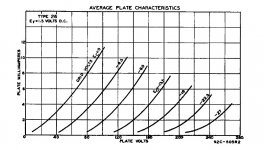
What is your operating point?
Attachments
Last edited:
Hi!
You are right 10V RMS in would be too much. I think he applied an input voltage which gave 10V out at 1kHz and then checked the other frequencies
Thomas
You are right 10V RMS in would be too much. I think he applied an input voltage which gave 10V out at 1kHz and then checked the other frequencies
Thomas
Another good choice for shielding is TI-Shield. It is a permalloy core sheet plated on both sides with copper, so it handles both magnetic and electrostatic shielding. I have used it in a few components and it really cuts down on the interferences. It also maintains its shielding properties when bent or soldered, which is an advantage over mu metal. It has a nice copper color if you care about the esthetics. Available at Michael Percy Audio. Here's some info on its construction:
http://www.emsclad.com/examples/emi-rfi-shielding.html
When I breadboarded my 26 preamp I had a lot of hum - what I found was that most of it was coming from nearby electrical devices, such as the lights inside the cabinet the pre was in, the overhead lights, an old tuner that was nearby, etc. unplugging/turning off those sources resulted in a decrease of hum of ~80%.
.
Last edited:
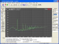
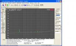
Here are a couple plots showing the background noise of a low frequency EQ unit I worked on. The first is the unit with no shielding around the power supply, the second is with a single layer of TI-shield around the power supply, grounded to the steel chassis. The power supply was in the same box as the audio circuits.
I did make some other mods to the unit that helped, but the majority of the noise reduction came from the TI-shield.
I did make some other mods to the unit that helped, but the majority of the noise reduction came from the TI-shield.
Attachments
Last edited:
Hi!
You are right 10V RMS in would be too much. I think he applied an input voltage which gave 10V out at 1kHz and then checked the other frequencies
Thomas
Yes
That's recycling!I cut them out of the legs of the coffee table which people trashed at the yard.
 😀
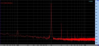
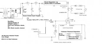
😀My (breadboarded) 26 pre spectrum (and THD) at 6V RMS output.
B+: 220V, filament bias (Rod Coleman supply) -1A with 10R- -10V, Majestic G-26 tubes, 6mA cascode (DN2540) CCS, 1K Riken grid stoppers, Shinkoh resistors on the input and output, 0.22uF russian FT3 teflon capacitor, S&B TX102 TVC.
Power supply on the another board (about 30cm distance): 2*240VAC-AZ1 mesh-CLCLC-(dual)SSHV2; 2*15V-FexFred bridge-C-CMC-CLC raw filament supply.
No audible hum.
Without TVC the bandwith over 300kHz (7Hz-320kHz +/-3dB)!
With different tubes (about a dozen) 50 and 100Hz components changing about 30db (-80..-110dB)!
Attachments
Last edited:
Whilst watching the women cycle race (on TV of course otherwise will be down the rain here in London 🙂 ), I did some first measurements on the Lundahl LL2745 that Thomas Mayer kindly send me as a trial:
http://www.bartola.co.uk/valves/2012/07/29/26-dht-preamp-with-ll2745-opt/
looks very promising so far, will now rebuild my 26 preamp and do some listening tests
Cheers,
Ale
http://www.bartola.co.uk/valves/2012/07/29/26-dht-preamp-with-ll2745-opt/
looks very promising so far, will now rebuild my 26 preamp and do some listening tests
Cheers,
Ale
Hi!!
Someone tried choke load and output transformer in parafeed configuration?
Maybe one of these can work?
EDCOR - XSM10K/600
http://www.edcorusa.com/Content/Plots/XSM10K-600.pdf
EDCOR - WSM10K/150
http://www.edcorusa.com/Content/Plots/WSM10K-150.pdf
Can be a more flexible solution...
Alberto.
Someone tried choke load and output transformer in parafeed configuration?
Maybe one of these can work?
EDCOR - XSM10K/600
http://www.edcorusa.com/Content/Plots/XSM10K-600.pdf
EDCOR - WSM10K/150
http://www.edcorusa.com/Content/Plots/WSM10K-150.pdf
Can be a more flexible solution...
Alberto.
Is there any way that someone could post a schematic of what would be considered a "best practices/results" design for this project?
There are almost as many designs as there are designers on this thread. Battery bias, filament bias, cap coupled, transformer coupled, autoformer coupled, parafeed coupled, choke loaded, CCS loaded, gyrator loaded, VC on input, VC on output, etc.
Take your pick, or mix and match.
Take your pick, or mix and match.
The two most important things IMO. Heater supply. (Rod Coleman's supplies are a no-brainer from what I've read) Still haven't implemented the ones I bought BUT I will.Is there any way that someone could post a schematic of what would be considered a "best practices/results" design for this project?
And the PSU.
The rest is pretty much taste.
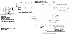
DHT-26 LINE: Serving Suggestion.
Thanks Bas! You can use the Regulators when you're itching for an upgrade some time!
A lot of taste is involved in getting a 26 DHT line amp to sound the way you like, but how about a sketch that gets a newcomer to the thread started? This should not be too controversial, I hope.
Based on properly implemented HV and filament supply, using good quality transformers, and a high quality Lundahl LL1660 output transformer to drive cable well.
I have showed filament bias, so that degradation due to cathode coupling caps can be avoided. Fil Bias generates lots of heat in the Bias resistor, buts gives the least compromise to the sound. (I can post a battery bias version if anyone would like it).
The circuit assumes that Sources have dc offsets below 0.2V, or a series capacitor will be required.
Attachments
Indeed..not controversial at all from my point of view. For the frugal though...The LL1660 output tranformers are relatively expensive though. Same for good anode/plate chokes (And layout/humm issues). A good CCS adds complexity.This should not be too controversial, I hope.
So I guess a plan B would be a simple RC version of your schematic above.
Say 22k plate load with 0,22uF coupling cap. A la 26 Menu
Last edited:
Rod's schematic is excellent. The way I have it I'd have 4.5v on the filament negative and 6v on the positive. 95v on the plate of the 26. My cathode resistor is 5 ohms, which is two 10 ohms 20W in parallel. I have 12v going into Rod's filament supply. I use LL1660/5mA (3mA actual current) in 1:1 because it's effectively the first stage of my amplifier rather than a stand-alone preamp. I actually slightly prefer the sound of two Hammond 156C plate chokes in series as discussed and a 0.1 FT-2 teflon output cap, but this is very prone to low level hum and can only be cautiously recommended. If you can deal with the hum it's a much cheaper option.
But actually, I'm using a 4P1L in filament bias with a 20 ohm filament resistor and a LL1660/18mA. I've moved on. It's a close call but I like the treble and clarity of the 4P1L.
Andy
But actually, I'm using a 4P1L in filament bias with a 20 ohm filament resistor and a LL1660/18mA. I've moved on. It's a close call but I like the treble and clarity of the 4P1L.
Andy
Last edited:
Thanks Bas! You can use the Regulators when you're itching for an upgrade some time!
A lot of taste is involved in getting a 26 DHT line amp to sound the way you like, but how about a sketch that gets a newcomer to the thread started? This should not be too controversial, I hope.
Based on properly implemented HV and filament supply, using good quality transformers, and a high quality Lundahl LL1660 output transformer to drive cable well.
I have showed filament bias, so that degradation due to cathode coupling caps can be avoided. Fil Bias generates lots of heat in the Bias resistor, buts gives the least compromise to the sound. (I can post a battery bias version if anyone would like it).
The circuit assumes that Sources have dc offsets below 0.2V, or a series capacitor will be required.
Sorry my ignorance, do you connect a 9V alkaline between cathode resistor & ground?
Sorry my ignorance, do you connect a 9V alkaline between cathode resistor & ground?
Hi Felipe, Battery bias schematic is here!
Attachments
- Home
- Amplifiers
- Tubes / Valves
- #26 pre amp