Toroid is good when it is a screened type - please try them! In UK, ask at Canterbury windings, or Air-Link. They both have 'audio' toroids, which have screens, and are high quality items. Trafos from Toroidy (Poland) and in the U.S. the Antek AS series [50VA and above] are also available in screened versions, and well worth investigating. The recommendation for EI trafos is still good, but screened toroids should have lower leakage capacitance and lower leakage inductance - both of which is helpful for noise control.
Rod - that's helpful information. I'd assumed you were against toroids in general, but it seems that was too simplistic.
For filament bias I've found that a choke input filament supply is audibly a little better. Even small improvement count when you want to optimise everything. You can use Hammond 159ZC which is 2A rated. The 159ZA is 1A rated if you starve the filament a little, which some like.
What are your thoughts on choke input, Rod?
Choke-input does not affect the output of my filament regulator - which are capable of reducing the ripple voltage from a cap-input supply down to the µV region.
But choke-input reduces the recharge current-pulses in the transformer/rectifier, and those might couple into the signal parts of the amp. Or they might couple back to the mains line voltage, and then corrupt another supply, like the DAC or MC preamp DC supply.
The best way is to keep all transformers, rectifiers and chokes away from the valves and the other signal parts. At least 1 metre!
If you can't do that, choke-input may well make a difference, but layout and wiring arrangement are still VERY important for good sound.
Speaking of wiring, when you use outboard supplies do you favour screened cable or is tightly twisted signal and ground OK?
DHT Filament supplies must be fed with a floating Raw DC supply. This means that common-mode noise pickup can be converted to differential mode noise at the cathode resistor (or filament bias resistor).
Most listening rooms have walls with AC-mains line voltage embedded, and this can look like being in the middle of a turn of a large coil, energised at 50/60Hz.
For sensitive preamp stages - especially low filament-current DHTs - may well benefit from wiring the raw DC with screened cable. For low currents, audio cable with a foil screen + drain-wire (example: Evolution XPC with 24AWG cores)
Evolution XPC 301-031 20M Professional Analogue Audio Cable 1-Pair Black 20m | Rapid Online
Taking spectrum of the preamp output will tell if it is worth doing this. Screening will not usually affect 100Hz/120Hz spurs, but could well improve things if there is a substantial 50/60Hz spur.
But if building a new preamp, I would suggest screened cable for the Raw DC, for sure.
At higher currents, you can use "CY control cable" - find it on ebay. CY has copper braid screen (make sure it looks fairly dense). Avoid SY, which is steel screened (unless you are afraid your home DIY might involve hammering some nails through you preamp supply cable, anyway)
Thanks. I was thinking of both HT and filament supplies, hence the "ground". Good to remind everyone that DHT filament supplies are floating.
Connectors are another story again. I've always found XLR 4 pin to be handy for DHT filaments. Can't think of any obvious alternatives. HT connectors are a whole different story.
Connectors are another story again. I've always found XLR 4 pin to be handy for DHT filaments. Can't think of any obvious alternatives. HT connectors are a whole different story.
I think the white output Powercons are quite a good idea at the PSU end. On the signal chassis, however, i think a Speakon is better. Doesn't matter of you plug a speaker into it - should do nothing assuming all the caps are discharged. You don't want to have anyone plugging the mains into a Powercon socket on the signal chassis. These are compromises, but military connectors are expensive and may require special tools.
> I was thinking of both HT and filament supplies
Coomon-mode noise pickup is less trouble for the HV supplies, so twisted cables should be good. A filter cap just inside the signal chassis is a good idea.
Coomon-mode noise pickup is less trouble for the HV supplies, so twisted cables should be good. A filter cap just inside the signal chassis is a good idea.
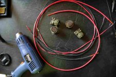
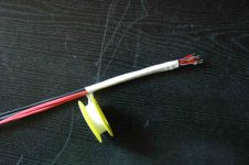
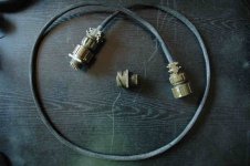
Umbilical
Some (8) years ago I made this umbilical, which is working even today -when this preamp working- between #26 preamp and his PSU box.
Lightly twisted silver plated teflon wires, each pair heatshrinked, then the all wrapped with teflon tape. Military (soviet) connectors.
Some (8) years ago I made this umbilical, which is working even today -when this preamp working- between #26 preamp and his PSU box.
Lightly twisted silver plated teflon wires, each pair heatshrinked, then the all wrapped with teflon tape. Military (soviet) connectors.
Attachments

Last edited:
...Ale's source follower at the bottom right...
Hi Ra7,
Just curious, why are you using a source follower at the output of your preamp?
What will you be driving?
I looked back through the thread, but could not find what I was looking for.
Best regards,
John
I was ready here to come here and declare victory, but ran into a problem right at the end.
The preamp with the gyrator board, source follower, and Rod's regulator all tested and powered up great. Put in the tubes, everything worked. Put it on for testing and it was making beautiful sounds. I listened to it all evening. No hum at all. Dead quiet at the listening position, small bit of hiss with ear near the 110 db/W horns.
Then I took it back to the bench to improve the UX4 mounting sockets. Pulled out the tubes and did some stuff, then put the tubes back and retested bias current and anode voltage. Everything checked out on the test bench. When I hooked it up to the DAC (RME ADI-2 Pro) and power amp (F4), both powered off when the preamp was turned on, it blew the fuse immediately. Fuse is a 0.5 amp fast blow on the mains (120 V). Still runs on the bench with nothing hooked up to it.
Pots on both the gyrator boards are working. The filament bias adjustments are working. Can't figure out what I did wrong the second time. I checked the connections and couldn't spot any shorts or anything else that is odd that I might have done while fiddling with the UX4 sockets. Really bummed out that it stopped working.
I can try isolating the problem, which clearly happens when it is connected to an external piece of equipment, probably to an external ground. Any hints on what might be going wrong and how to troubleshoot?
Last edited:
Blowing the mains fuse when connecting to other equipment can be caused by failure of the isolation between the mains (line) voltage and the chassis or the 0V of the preamp. Since this is potentially a safety hazard, it should be checked for, before anything else.
Portable equipment safety-test equipment will pick this up, if you can't see or measure the fault yourself, you could get a domestic/office electrical technician to test it.
Is the chassis solidly connected to safety ground? Is the 0V of the HV supply connected to safety ground/earth + chassis? It really should be. If it is, there should be no difference when connecting to another piece of equipment.
The 0V is connected to safety earth through a CL60 thermistor. The chassis is directy connected to the saftey earth from the IEC plug.
The thermistor raiser a small barrier to prevent a ground loop but it it small enough that if higher currents flow, they will get shunted to earth.
The thermistor raiser a small barrier to prevent a ground loop but it it small enough that if higher currents flow, they will get shunted to earth.
Last edited:
ra7,
Since both the 0V and the chassis are earthed then start visually inspecting everything. Normally, you can see where something went wrong on reassembly. Then check the input / outputs for voltage to ground.
Since both the 0V and the chassis are earthed then start visually inspecting everything. Normally, you can see where something went wrong on reassembly. Then check the input / outputs for voltage to ground.
The 0V is connected to safety earth through a CL60 thermistor. The chassis is directy connected to the saftey earth from the IEC plug.
The thermistor raiser a small barrier to prevent a ground loop but it it small enough that if higher currents flow, they will get shunted to earth.
You've tried bypassing the thermistor directly to the chassis? And checked any voltages on input and output connectors, both AC and DC?
I started measuring across the thermistor and it was showing very low ohms, in the 0.3 ohm range. When cold it should read about 10 ohms. So, after some sleuthing, it turned out that the gyrator board standoff holes are connected to 0V on the board. This didn’t affect anything as far as I can tell, but was good to fix. I was careful on the SF board to not connect the holes to the chassis.
The real problem appears to be that the fast blow 0.5 amp is just wrong for the mains. I have it back running after bringing it up with a variac. It blew a couple of fuses at random on the bench when there was nothing wrong but always worked with the variac. I think the last evening when I had it running, just got lucky that the fuse didn’t blow.
So, I have it running for now and will wait until the slo-blo 0.5 amp fuses arrive. Will just have to remember to use the variac to turn it on slowly. I also turned on the DAC first this time. Something to check. I’ve been through 8 fuses already and have just two left. More testing to come. Happy holidays everyone!
ra7,
Since both the 0V and the chassis are earthed then start visually inspecting everything. Normally, you can see where something went wrong on reassembly. Then check the input / outputs for voltage to ground.
You've tried bypassing the thermistor directly to the chassis? And checked any voltages on input and output connectors, both AC and DC?
Thanks George and Andy. Both AC and DC measure zero on input and output. The problem is fixed for now. Time will tell if the slo blow fuse solves it permanently.
- Home
- Amplifiers
- Tubes / Valves
- #26 pre amp