Groundfill cuts
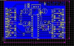
This is what I did to the groundfill - I introduced a cut so that the large currents on the output side won't introduce any voltage drops across the signal side. Doing this necessitates cuts on both sides of the PCB - right across on the top side and through two wide 0V tracks on the bottom side.
Performing the cut on the top side means the heatsink has to be removed - unscrew the two mounting screws from the MOSFET and the temperature sensing transistor and then it can be desoldered - there are two pins into the PCB. The cut runs along the silkscreen marking for the heatsink just beyond the mounting pins.
I joined the two separated fill areas together with a wire between the output -ve and pin2 of the IRS2092.
Attachments


@abraxalito Would you kindly explain briefly what are the benefits of such operation? Is it also relevant for the L-25D which I have? Also; Do you reckon that all L-xxD models sound the same. - I mean, that only difference is the output power?
Cheers!
Cheers!
Subjectively the combined mods - adding caps and separating the fill into two parts - have given a worthwhile reduction in the fatigue factor of listening. When I first fired up the amps they were a tad harsh in the HF but that's pretty much all disappeared now. I still get a little harshness at times but it seems that's on the recording itself rather than introduced by the amp.
Do you have links to all the other models you refer to? I'm not really up to speed with other LJM amps.
Do you have links to all the other models you refer to? I'm not really up to speed with other LJM amps.
hello guys
What do you think about PT2325 for volume control?
I plan to use PT2328 with WIMAs MKS2 1uF 63V 5%
On schematic one resistor and capacitor have no value.
Will 100R be good and 100nF ?
Thanks
I modded a Sony BDV-E2100 with 3 PCM5102A as DAC 🙂 Works great.
What do you think about PT2325 for volume control?
I plan to use PT2328 with WIMAs MKS2 1uF 63V 5%
On schematic one resistor and capacitor have no value.
Will 100R be good and 100nF ?
Thanks
I modded a Sony BDV-E2100 with 3 PCM5102A as DAC 🙂 Works great.
Attachments
Last edited:
Subjectively the combined mods - adding caps and separating the fill into two parts - have given a worthwhile reduction in the fatigue factor of listening. When I first fired up the amps they were a tad harsh in the HF but that's pretty much all disappeared now. I still get a little harshness at times but it seems that's on the recording itself rather than introduced by the amp.
Do you have links to all the other models you refer to? I'm not really up to speed with other LJM amps.
Hi
here they are:
L30D:
1pcs L30D 300 850W IRS2092S MOSFET IRFB4227 Digital Power Amplifier Finished Board by LJM-in Amplifier from Consumer Electronics on Aliexpress.com | Alibaba Group
Assembled L30D 850W Digital Mono Power Amplifier Board IRS2092 IRFB4227 IRAUDAMP9D Audio Amp Module-in Operational Amplifier Chips from Consumer Electronics on Aliexpress.com | Alibaba Group
L20D
L20D 300W+300W Class D IRS2092 IRFI4020 Power Amplifier Completed board LJM-in Amplifier from Consumer Electronics on Aliexpress.com | Alibaba Group
here some different L15D versions...nearly endless version existing ..
L15D PRO 300W Class D IRS2092S Digital Amplifier Mono Board w/ Relay Protection-in Amplifier from Consumer Electronics on Aliexpress.com | Alibaba Group
with PSU:
300W 4R Mono L15D IRS2092 + IRFB4019 Digital Amplifier Board 63V5600UF Original Capacitance 10 15A Fully Sealed Relay-in Amplifier from Consumer Electronics on Aliexpress.com | Alibaba Group
chris
Ah, thanks. The L25D is an implementation of the IRAUDAMP7 but has significant differences so lots of the mods I'm doing to the L15D-SMD won't be applicable. For example its not using external regulators for the pin1,6 power supplies - I guess its relying on the internal zeners for this. Increasing the cap sizes definitely brings benefits in dynamics with this topology, as I found a few years back on this thread with an earlier LJM board.
I notice also that the L25D is using separate FETs rather than the 'duo' FET as on L15D-SMD. There are bound to be substantial differences in the PCB.
I notice also that the L25D is using separate FETs rather than the 'duo' FET as on L15D-SMD. There are bound to be substantial differences in the PCB.
Thanks for the links @chris - I see that the L30D is a very high power design with additional transistors for driving the output FETs as they're large, low RDS(on) devices. Its based on a very cut-down IRAUDAMP9 schematic.
The L20D is another IRAUDAMP7 incarnation, it also is using the internal zeners on the IRS2092 for the power supplies. The give-away is the two high wattage resistors visible and the lack of any other discrete/integrated reg. Here's what IR/Infineon say about those power supplies (AN-1138, p14) :
For best audio performance, it is preferred to produce VAA and VSS with external regulators, such as three terminal regulators.
The alternative is using the IRS2092's internal zener diodes but it seems to me that IR's recommendations for the current needed for them aren't high enough. The appnote says 10mA supply current should be allowed for but I am seeing a quiescent of 9.5mA (for the analog circuitry, excluding the zeners) so this to me says the zeners are going to run on 0.5mA - resulting in a high dynamic impedance.
To answer your earlier question @Guerilla, no I don't think they'll all be sounding the same. The power supply quality is the primary determinant of SQ and only the L15D-SMD (that i've seen so far) has external regulation for these critical supplies.
You're welcome, I'm having fun here poking around with my L15DSMDs and seeing how much I can learn about the IRS2092 🙂
Since I posted about the internal zeners I've made another minor discovery - the figure I gave before is too pessimistic (0.5mA for the zeners). It seems the zeners conduct a little bit even below their rated voltage - I discovered this by lowering the analog supplies (pin1,6) by about 0.6V and found the current draw decreased by about 1mA. I now prefer to run those pins at +/-5V and with those voltages, the draw on those two PS pins is ~ 8.5 to 9mA. So this leaves up to 1.5mA for the zeners - still not enough in my estimation but better than my earlier number of 0.5mA .
Looking at 5V zeners I see a typical dynamic impedance in the region of 500ohm for 1mA. With the 47uF in parallel as on L20D and L30D, the cap would dominate the impedance seen over the audio band (at 20Hz, 47uF is ~170ohm). On the L15DSMD with EFs feeding the supply pins we would get ~ 3ohms at LF, a huge improvement.
You're welcome, ......
Looking at 5V zeners I see a typical dynamic impedance in the region of 500ohm for 1mA. With the 47uF in parallel as on L20D and L30D, the cap would dominate the impedance seen over the audio band (at 20Hz, 47uF is ~170ohm). On the L15DSMD with EFs feeding the supply pins we would get ~ 3ohms at LF, a huge improvement.
Hi
sorry i am a noob - What is EF´s
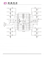
No worries - EF is EE shorthand for 'emitter follower'. If you look at the IRAUDAMP7S document, fig33 (p30) has an example : Q105 is configured as an 'EF' to power the VCC. The input is the base and that's held at a fixed voltage by the 15V zener - the unregulated power goes in via the collector and exits from the emitter (the terminal with an arrow on it).
Incidentally this is the pattern that's been copied on L15DSMD to feed pin1 and pin6, except that the zeners are 6.2V instead of 15V.
Incidentally this is the pattern that's been copied on L15DSMD to feed pin1 and pin6, except that the zeners are 6.2V instead of 15V.
Last edited:
Mods list, part one
Here I'm going to set out the mods in more detail. Not all of these mods I've done because I think they'll improve the SQ, some are just because I've noticed some stuff isn't really optimized, particularly in terms of running from my target rails of +/-36V. The stock board's voltage rails (judging from the silkscreen) are 40-60V, in some cases I've made changes because it won't work properly at 36V in stock form. If someone wants to eek out more watts then propose your own rails and I'll have a stab at optimizing for them.
The component numbering I'm taking from the IRAUDAMP7S document, this is largely followed in the silkscreen but I haven't checked all references there.
First off - the VCC (pin12) power supply. VCC is the rail for powering the low-side gate driver and dead time circuitry.
a) R21 (10R) is reduced to 3R which reduces the LF impedance of the rail.
b) R114 (1k, 1W) replaced by a string of 4 22R 1206. This resistor's value looks chosen for higher rail voltages - its mostly unnecessary as the transistor it feeds is on the heatsink.
c) CP101 (47uF/50V) increased to 470uF/16V
d) R115 lowered to 6k8 to increase the zener current at the lower rail.
e) Z102 (15V) reduced to 2 * 5V6 (or 1 * 11V, I don't have those to hand)
f) CP5 (47uF/50V) increased to 1800uF/16V
For the gate drive circuitry:
g) R24,25 (20R) lowered to 10R - increasing the switching speed of the FETs
h) R27 (10k) removed, reducing the dead-time to 25nS (typical).
more to come....
Incidentally this is the pattern that's been copied on L15DSMD to feed pin1 and pin6, except that the zeners are 6.2V instead of 15V.
Hi Abraxalito,
in case that I modify my L20 with emiter folowers for the regulation of pins 1 and 6, would you recommend 15v or 6.2v for the zener? Asuming +- 55v rails?
Hi @Ricren - for EFs powering pins1 & 6 I recommend 5.6V zeners. You'll need resistors feeding the zeners to be 24k, 1/4W rating. The EFs will run warm, about 0.5W dissipation. A TO-220 should handle it without a heatsink.
Hi @Ricren - for EFs powering pins1 & 6 I recommend 5.6V zeners. You'll need resistors feeding the zeners to be 24k, 1/4W rating. The EFs will run warm, about 0.5W dissipation. A TO-220 should handle it without a heatsink.
Excelent.I''ll do it. Thanks a lot .
Great - do report back how the sound changes with the EFs in place 🙂
A couple of points - I suggest 5.6V rather than 6.2V for the zeners because I found during my experiments that the zeners on the IRS2092 start to conduct slightly above 5V on the supply pins. Keeping the supply no greater than +/-5V keeps the chip's dissipation to the absolute minimum.
Second - if you prefer to use a resistor in series with the collector of the EF you can likely use a physically smaller transistor than a TO-220, perhaps a TO-92. The collector resistor's value should be 3k3, 0.5W rating.
Great - do report back how the sound changes with the EFs in place 🙂
A couple of points - I suggest 5.6V rather than 6.2V for the zeners because I found during my experiments that the zeners on the IRS2092 start to conduct slightly above 5V on the supply pins. Keeping the supply no greater than +/-5V keeps the chip's dissipation to the absolute minimum.
Second - if you prefer to use a resistor in series with the collector of the EF you can likely use a physically smaller transistor than a TO-220, perhaps a TO-92. The collector resistor's value should be 3k3, 0.5W rating.
Thanks, I'll try that. How about some caps parallellng the zener and some big at the emiter?
- Home
- Amplifiers
- Class D
- 200W IRS2092 Amp for $20