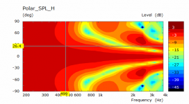
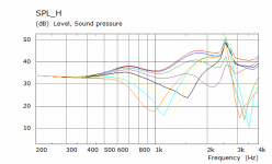
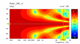
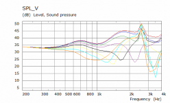
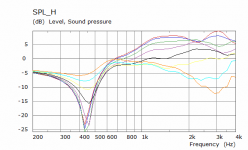
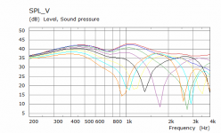
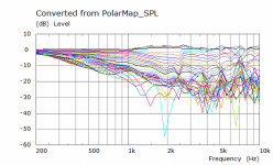
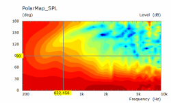
Here are the simulation results of the 4 Sica Chambers placed closer together. This does a good job of reducing the lobing in the range of interest but it has also created very little directivity and may not be an ideal match to the waveguide. Extending the directivity would result in more lobing which is no surprise. Some difference between H and V this time, probably because of the side slits at this distance.
Attachments
going full on array physics can you drive additional out of phase units to beam shape in a way that gets rid of the lobes?
Yes you could if you created a situation where the destructive cancellations were unable to form.
The cancellation is what creates the directivity so it is necessary to some extent.
What you are suggesting would probably be better investigated with Vituix or the Direct Sound part of ABEC due to the speed they offer.
The addition of the Sica drivers has already made this more complicated than I originally wanted so adding in extra drivers and channels in this range is outside anything I want to tackle right now.
It seems like the woofer slots have to be closer together which will degrade the performance of the horn 🙁
I guess it would be a cool design if one wants to combine it with a MEH, or a coax CD that goes down to 300hz 🙂
I guess it would be a cool design if one wants to combine it with a MEH, or a coax CD that goes down to 300hz 🙂
So here are the graphs, simulating the same "egg" shaped horn with and without the ports. With only a flat disc radiating.
Addiing the slots doesn't introduce much change to the HF response


Addiing the slots doesn't introduce much change to the HF response
I simulated the step you sent me to see the effect of the ports on the waveguide response. I left the wrong frequencies from a previous simulation in the script so I only have data to 4K but I get the same dip as I did before in my first attempt.


Attachments
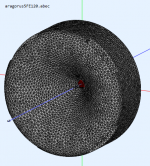
Here is something that seems interesting. I made a simplified model at a coarser mesh resolution and used a flat disc as a driver instead of a cone, dust cap and surround. This actually has some directivity at 500Hz down so could perhaps integrate with the waveguide better.


Attachments


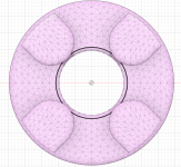
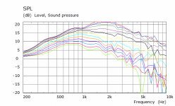
Given that the previous ring chamber had some redeeming features and was not a crazy amount of elements I moved on to see what effect it would have on the basic waveguide response.
This post has the raw waveguide results as a baseline the next post will have the ring added.
This post has the raw waveguide results as a baseline the next post will have the ring added.
Attachments

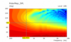
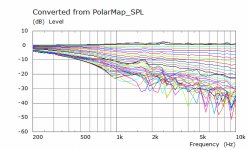
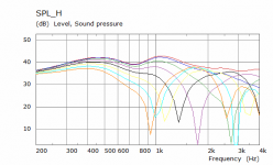
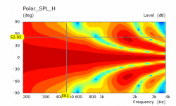
With the ring added, it is not as pretty but more of the basic shape is retained than it was with holes in the horn. I don't think I have optimized the size of the ring relative to the waveguide or how far behind the ring needs to be to limit it's effect on the waveguide yet.
Attachments
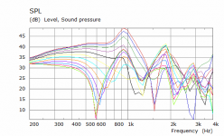
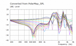
That looks like a very usable response. I don't see a reason to care about that far off axis null circa 600 Hz. That must be slots on opposite sides of the doughnut combing.
The near axis response isn't completely flat but I would bet it will be hard to do better over such a wide range in the same size waveguide.
The near axis response isn't completely flat but I would bet it will be hard to do better over such a wide range in the same size waveguide.
It's there in the graph of the ring without the waveguide but is less pronounced. Making the ring smaller could push it a little higher to be further from the intended passband. It is more coaxial in nature than using another waveguide or woofer directly below to cover those frequencies but is it worth it?That looks like a very usable response. I don't see a reason to care about that far off axis null circa 600 Hz. That must be slots on opposite sides of the doughnut combing.
The near axis response isn't completely flat but I would bet it will be hard to do better over such a wide range in the same size waveguide.
It could be but the raw directivity of the waveguide is not improved with adding extra bulk behind it. I wanted to see if there was a way to keep that with adding something extra to mount the woofers.Maybe somehow improving the transition of the horn to the back piece could be helpful..
The best compromise may well be something like the egg you showed and as you did covering over the ports to compare against the raw guide is relatively simple.
That may work as a single exterior subdomain as I still cannot get a freestanding guide with thin profile to simulate correctly without an interface.
If you mean "thin" as wall thickness then you might try NUC=true. Close parallel surfaces are a problem if NUC=false.
I might give it a try, thin wall thickness in this context is 8 to 10mm. Perhaps because that is close to the edge length of the elements it is having trouble. In circsym the mesh frequency is 30KHz, that might explain it.
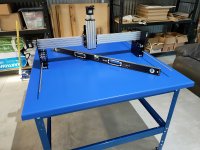
Starting to resemble a CNC

Table is level from corner to corner but you can see the dip in the middle due to a lack of reinforcement there. Should be good enough as I am not using the table as a cutting bed but it can be dealt with if need be.

Table is level from corner to corner but you can see the dip in the middle due to a lack of reinforcement there. Should be good enough as I am not using the table as a cutting bed but it can be dealt with if need be.
Attachments
I am still working on making these ideas into reality. Just as I finished building the CNC kit I realised that I really hate V wheels and that would only be more annoying over time. The table I built was also not big enough to mount an enclosure to 🙄
I now have the parts for an upgrade to the CNC, linear rails, heavy duty plates to give more Z height and overall rigidity and extra extrusions to make the whole thing more solid. I was nervous that the plates might not be right but I was pleasantly surprised that they are 10mm thick and as flat as my Starrett straight edge. The rest of the upgrade kit seems very well thought out so fingers crossed this is as far as I need to go. There is going to be a v-slot extrusion torsion box with a birch ply top big enough to build a proper enclosure on.
I also bought a 3D printer to make some parts for the CNC and possibly for waveguide and MEH related tests at a later date. I hoped it was going to be an easier setup. Even though it didn't seem to suffer from terrible QC it still took me 5 hours today to properly align the gantry and bed as neither were responding well to popular youtube methods. Seems to be working well enough for basic printing. I can see properly calibrating it will be a bigger time drain than I hoped and resisting the urge to upgrade and tinker will be difficult.
- Home
- Loudspeakers
- Multi-Way
- 2 way waveguide speaker build ABEC modelling