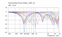
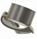
I have been intrigued by the Genelec "One" series as they have very consistent directivity for quite a small speaker. I have simulated something similar to the concealed woofer idea but with the dimensions of the 5" Sica drivers I have. In this iteration the cone is driven directly without any lumped element model to get a better idea of the raw directivity. The bandpass peak is evident but for use from 500 to 800Hz down then it seems it might be quite workable if I can find a way to fit this behind the free standing guide in some form of array.
Attachments


I've simmed a mirrored array of 4 drivers but the sim time went from 13 minutes to 3 hours so I haven't got the graphs prepared yet but I will later.
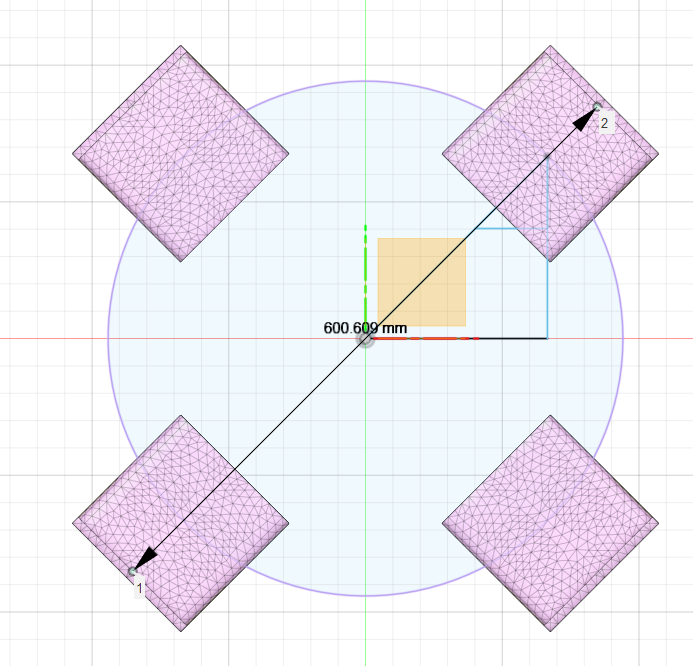
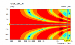
I guessed wrong with the dimensions so the CTC distance was bigger than intended, it shows the array effect and directivity though.
I guessed wrong with the dimensions so the CTC distance was bigger than intended, it shows the array effect and directivity though.
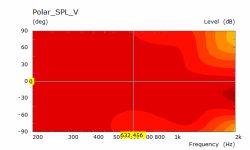
I made a mistake with the distances of the first mirrored copies so the cancellations/nulls come in lower than intended. I have rectified it but the sim is still running. These are the results of the other one. By having the horizontal and vertical the same distance the polar remains consistent to hopefully match the waveguide.
Attachments


So sound from the bandpass midwoofers is going to propagate/diffract around the rolled back waveguide termination? I don't doubt that it will, save possibly some shadowing on axis but I see you normalizing to 20 degrees off axis. That changes things...you might even want to leave off the 4th driver, the one furthest from your observation angle.
At 500Hz and below there shouldn't be a massive issue with diffraction, the idea is to have the main exit from the bandpass chamber be inline or slightly above the waveguide rollback as in mabat's sims sound from directly behind that has to negotiate the rear rollback struggles to get there.
I need to build the sims in layers to see what is happening before moving to the final installation, the elements get out of hand quickly and I will have to simplify some parts to have any hope of seeing the whole picture together in a simulation.
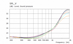
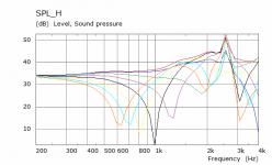
It is actually normalized to the on axis 0 degrees not 20. The H SPL has no normalization and represents a more real view as would be measured without EQ.
I need to build the sims in layers to see what is happening before moving to the final installation, the elements get out of hand quickly and I will have to simplify some parts to have any hope of seeing the whole picture together in a simulation.
It is actually normalized to the on axis 0 degrees not 20. The H SPL has no normalization and represents a more real view as would be measured without EQ.
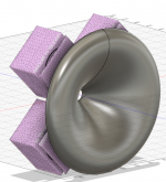
Cool concept. Would the bandpass boxes work better if they where rotated so that the driver magnets where perpendicular to the horn axis? (blue) (this would let you get them closer to together I think from the pictures you have shown and interfere with the roundover less)
This is what was intended
That is a very cool idea. Were you able to do 1/4 symmetry or actual IB mirrors ?
This might be even more complicated fabrication wise but could the mid drivers load a open sided torus shaped horn that used the CD horn round over as the inside transition? The mids could closely surround the CD facing forward also.
Last edited:
This is what was intended
I half expected you to use the waveguide-rim to create the band-pass for the woofers. (sort of integrated into it, much like Genelec)
Making it compact and lots of freedom to make it look pretty. 🙂
I'm not sure it would be better as I would think it is the CTC distance of the slots that matters, I also think the slot needs to be on or above the waveguide but that has yet to be confirmed as necessary. If it wasn't that would change things.Cool concept. Would the bandpass boxes work better if they where rotated so that the driver magnets where perpendicular to the horn axis? (blue) (this would let you get them closer to together I think from the pictures you have shown and interfere with the roundover less)
I did quarter symmetry and mirroring of the half cut model I had before. The second part was more laziness to avoid having to undo all the cuts and hiding of elements in Fusion to create a full box mesh.That is a very cool idea. Were you able to do 1/4 symmetry or actual IB mirrors ?
I might need a sketch to understand what you are suggesting here 🙂This might be even more complicated fabrication wise but could the mid drivers load a open sided torus shaped horn that used the CD horn round over as the inside transition? The mids could closely surround the CD facing forward also.
Attachments

I half expected you to use the waveguide-rim to create the band-pass for the woofers. (sort of integrated into it, much like Genelec)
Making it compact and lots of freedom to make it look pretty. 🙂
So did I 😀
I did try something like that but it got pretty complicated and the rear volume needed ended up pointing up. It could be refined but I am concerned that it will still damage the polar more than I was hoping for 😉
If the current idea works out in simulation then I think I know how to integrate it and make it look better than what has been shown 🙂
Attachments

I had something more simple in mind


Seems to work up to around 700hz and then it breaks up into lobes
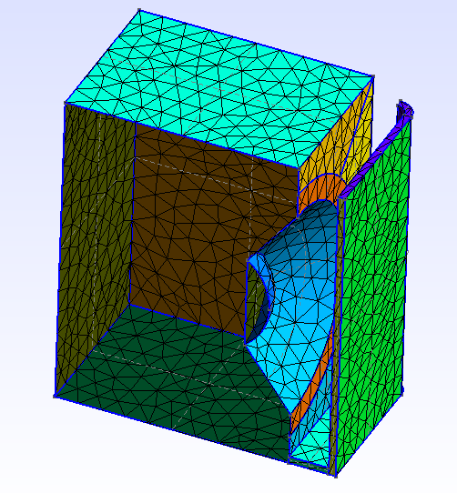
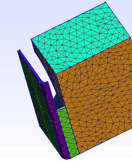
PS: Attaching things to curved surfaces scares me 😀 I always try to work from solid cubes (unless simulating the reflex box with BEM which sometimes works well)
Seems to work up to around 700hz and then it breaks up into lobes
PS: Attaching things to curved surfaces scares me 😀 I always try to work from solid cubes (unless simulating the reflex box with BEM which sometimes works well)
Last edited:
That is closer to what I would try and do but I wanted to keep the two separate at this point to see if I could keep the benefits of the rollback termination.
I am limited in some ways by having already bought 5" drivers as the physical size won't allow for every possibility. I'll explore those first before considering other sizes.
What size driver and waveguide were used in the images?
I am limited in some ways by having already bought 5" drivers as the physical size won't allow for every possibility. I'll explore those first before considering other sizes.
What size driver and waveguide were used in the images?
I was aiming for the faital5fe120, but I think I made them smaller 😀
However, you can always angle them a bit towards the horn wall, this way they should fit 🙂
However, you can always angle them a bit towards the horn wall, this way they should fit 🙂
Could you send me the step to look at so I can revolve it around?
There is also a bit of difference between horn profiles as to which give more space for different orientations.
There is also a bit of difference between horn profiles as to which give more space for different orientations.
Radius of 3.84cm give or take which gives an Sd of 46.32cm2 which is about 40 less than the 5FE120.I was aiming for the faital5fe120, but I think I made them smaller 😀
However, you can always angle them a bit towards the horn wall, this way they should fit 🙂
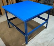
I think angling the driver and reducing the front chamber a little would probably be good. A hybrid between this and my test box should work nicely in the space.
Did you compare the result of the raw waveguide to the response with the chamber cut in? I meshed it at 10mm but at nearly 5000 elements it will take a while to solve and I don't have the raw waveguide to compare.
- Home
- Loudspeakers
- Multi-Way
- 2 way waveguide speaker build ABEC modelling