fluid ... or anybody familiar with the syn horn ... is it possible to make a lengthened throat that includes an entry for the mid(s)? The CD would enter the horn on a straight pipe and the mid(s) would mount on a fixture that has a swept pipe port that connects to the CD's straight pipe before the horn. So, a multiple entry throat.
In my previous Hornresp sims minimising port length and matching that to the appropriate chamber volume is the key. The diameter of the port has already gone from 20mm to 32mm as my quick calculation for a 10:1 compression ratio was wrong 🙄 The drivers should be here today so I can get a better idea of the volume of air that will be trapped under the cone.The length and diameter of the port do effect the response shape sometimes very strongly for mids and you want to check the particle velocity.
Me neither and that is a good suggestion having the entry/exit as smooth as possible. This falls into the category of how to do that with the CAD program, I'm figuring out a lot of it as I go as I am no CAD expert.I've no idea whether the amount of diffraction from the ports matters at all, but it struck me that they could be more rounded, as you have low diffraction as a goal.
It makes sense to be able to get down to 100Hz from something that will behave as a point source. These are woofers, not mids, 4 x 5" drivers instead of 2 x 10 to 15" drivers. The symmetry is useful in the first instance as it will allow a quarter model to be used to get a basic appreciation of what is happening. Beyond that the position, symmetry, number of drivers etc. can be adjusted.I'd missed that you were planning four ports. It's not clear to me that makes sense for home use. If you introduce four sources of diffraction in an arrangement that's highly symmetrical about the center line of the WG, you risk boosting their effect by interference (leading to bigger ripples and stronger excitation of one or other of the higher order modes). For home use, I would tend to lose an octave of mid-range response at the low end, and settle for one port rather than four. I guess you could make a WG with four ports, and also make three plugs, and test both ways.
It's possible but it would create a beamy horn and having the ports closer does make their effect on the waveguide larger.is it possible to make a lengthened throat that includes an entry for the mid(s)?
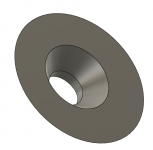
For my first try I'm just sticking with a 20mm port rounded on the front and chamfered on the back. If I can model this successfully in ABEC I'll have a better idea of whether this is worth taking further or not.
Now the 1L chamber makes sense 🙂
Is your CNC up and running ?
I have got some form of a plan even if it isn't clear to anyone else 🙂Now the 1L chamber makes sense 🙂
No not yet, as always something else keeps getting in the way but slowly I am getting there. I'm using the time to get some CAD models ready so I will have something to build. I'm hoping that will encourage me to find a way to squeeze it in.Is your CNC up and running ?
The 1500 x 1000 version of this
WorkBee CNC Wood Router Kit – Bulk-Man 3D
which then needs a table, a router, etc......
WorkBee CNC Wood Router Kit – Bulk-Man 3D
which then needs a table, a router, etc......
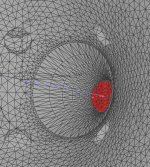
I have made some progress with the MEH simulation. The good news is that I have got something to work the bad news is that it doesn't work that well. I started with a freestanding horn but to get any kind of resolution the number of elements got too high. Those simulations thrashed around overnight and got nowhere.
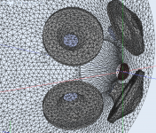
I went to infinite baffle, the difference between cutting holes in an Ath Mesh and using a stub throat mesh and the rest solid reduced the sim time from over 5 hours for the cut mesh to 1:40 for the stub mesh and the results were virtually identical.
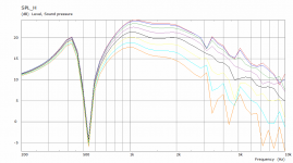
There is spiking from numerical issues which hides much of what the ports are doing and they aren't optimized because that is actually much harder to do with surfaces in Fusion.
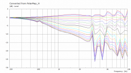
What does make sense is to use the BEM model to see what is happening with the driver and throat chamber and get that better before trying to add it into the horn.
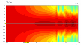
I will probably try moving the ports out as they are too close for the intended purpose and as that is in the parametric section it shouldn't be that hard. The big cancellation dip is not in a good place either. The polar is still consistent all the way round so one port in each quadrant didn't change that.
I went to infinite baffle, the difference between cutting holes in an Ath Mesh and using a stub throat mesh and the rest solid reduced the sim time from over 5 hours for the cut mesh to 1:40 for the stub mesh and the results were virtually identical.
There is spiking from numerical issues which hides much of what the ports are doing and they aren't optimized because that is actually much harder to do with surfaces in Fusion.
What does make sense is to use the BEM model to see what is happening with the driver and throat chamber and get that better before trying to add it into the horn.
I will probably try moving the ports out as they are too close for the intended purpose and as that is in the parametric section it shouldn't be that hard. The big cancellation dip is not in a good place either. The polar is still consistent all the way round so one port in each quadrant didn't change that.
Attachments
It is a good sample to see what trends are created by the holes. The effect on the higher frequency part due to disturbance created.
Too bad the higher res models don't seem to create better results, because that would have been easier for some overnight experiments on
shapes and sizes of the holes, maybe even with some combined guide leading up to the hole, protruding or trench shaped.
Too bad the higher res models don't seem to create better results, because that would have been easier for some overnight experiments on
shapes and sizes of the holes, maybe even with some combined guide leading up to the hole, protruding or trench shaped.
Last edited:
would it be easier to do this kind of simulation first on a crude flat sided conical horn where ports would be so much easier to draw
I saw this in another thread, it might be another avenue for improved taps:
COHERENT MIDRANGE INTEGRATOR (CMI)
COHERENT MIDRANGE INTEGRATOR (CMI)

I saw this in another thread, it might be another avenue for improved taps:
COHERENT MIDRANGE INTEGRATOR (CMI)
that´s a very interessting post!
If understand correctly, we should change the midrange input ports in MEH from classical "on-slot-ports" to several oval input ports. Port area will then be the same, just splited into several ones?
Second change is to make the input ports not as mostly made in 90 degree to the midrange basket. Instead input ports should be directed to the horn throat / high frequency driver.
yes although overall hole area may have to increase as there is a boundary layer at the tube wall so having more tubes will increase viscous drag. Its probably easiest to simulate a conical horn in order to test these ideas.
Really interested to see measurements/sim of this kind of approach, but i'd bet it still doesn't hold a candle to the stuff being done with ath4 🙁
The simulation I did was really just a proof of concept that I could model something that would work and simulate reasonable results.
The CMI seems like a good approach, it would be time consuming to replicate in CAD but doable and does aim to reduce most of the problems that can be seen in the simulations I did. Worth reading that page as a good primer on the issues that horn porting can give.
I agree with PKsound that it would actually be quicker to print something with a 3D printer and test it as getting things right to simulate it is quite time consuming. Parts of the problem could be broken down and simulation done on those to optimise the individual issues.
I will still try to move the ports out and make the overall chamber less of a disaster (just to see what difference it makes) but I have a better idea to try first that does not need any penetrations in the waveguide.
Modelling the ports on a conical guide would be much easier but then as the horn itself is not as smooth or consistent determining the more subtle effects would be harder.
Hey fluid!
I'm going through a similar process getting my coax MEH to simulate in AKABAK. Sometimes the simulations looks reasonable, and sometimes really weird.
I'm trying to incorporate the LEM side of things, as I would like to see how the crossover will work. That isn't exactly easy either 😀
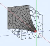
I did the model from scratch as a complete solid cube with the horn contour cutout for the first sim. and started building on top of that.
Seems like I should up my polygon count 😀
Your sims looks quite nice!
I'm going through a similar process getting my coax MEH to simulate in AKABAK. Sometimes the simulations looks reasonable, and sometimes really weird.
I'm trying to incorporate the LEM side of things, as I would like to see how the crossover will work. That isn't exactly easy either 😀
I did the model from scratch as a complete solid cube with the horn contour cutout for the first sim. and started building on top of that.
Seems like I should up my polygon count 😀
Your sims looks quite nice!
Attachments
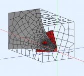
I think that route much like the Danely SM60 is a smart way of getting a big mid driver to work especially as the inner part of the horn can double as part of volume filler for the cone. I can see that there is something in front of your cone that is see through from the front side. Could you take a screenshot of the other way to see what you have to join the cone to the backside of the guide?Hey fluid!
I'm going through a similar process getting my coax MEH to simulate in AKABAK.
Getting the density of the mesh right is tricky as well as getting the vertices of the mesh to align if things are split.Seems like I should up my polygon count 😀
Your sims looks quite nice!
One tip if you have made the horn contour in Ath is to export it from ABEC as an STL file, import that into CAD, cut it on one of the profile lines with a plane created from on the vertices. Then create a polyline out the edge and use that to cut the solid waveguide. When you export both you can combine them back together with the vertices aligned as gmsh will mesh to the cut vertices on the solid waveguide. That way you have a higher density from the driver to the cut based on mabat's geocode which is much better than anything gmsh can do on its own. Then you can use a lower density on the outer parts. This took my simulation from 5 hours plus to 1 hour 40 with exactly the same result. I can see you had the same problem I did where gmsh is putting too many elements to describe the port. By setting the maximum and minimum element sizes to 10 it won't do that as much and put more over the whole surface. I also like to use the flat driver from the Ath model too rather than an ABEC created one like in your drawing. It helps to align the vertices again.


- Home
- Loudspeakers
- Multi-Way
- 2 way waveguide speaker build ABEC modelling