Hi Bach On,
Thanks for the additional pictures. Those are tight looking shades, just out of general interest, how are they actuated?
Regards,
Thanks for the additional pictures. Those are tight looking shades, just out of general interest, how are they actuated?
Regards,
@Bach On
Nice pictures!
I take it from the pictures that the PVC pipe air transfer conduit is to the left of the doorway. Quite a height up there to gain access!
You will be wanting to put the drivers into your new enclosure after you place your enclosure.
And I liked the view from the top of the bourdon rank. Looks like they were refelted sometime in the past.
@bentoronto
I can't argue with measurements. They stand on their own merrit measuring the conditions at the time of the test.
What I can say is that a measurement graph in absense of the cabinet dimensions and measurement placement postitions etc is hard to discuss.
Just one variable such as the crossover slope being diffeent than the one I used can make a difference.
Another variable is the cone type and diamter. Number of braces and placement within the enclosure. Are they shelf type or full width and length braces? All these factors change the measurement outcome. Was their enclosure a cube? It is the worst scenario for resonances.
What I can say with confidence is that Rod Elliot knows his stuff, and that he is careful to post things he knows are true.
AFter I wrote that little paragraph I thought I owed you a look at the references. They are great examples of how to effect changes within an enclosure.
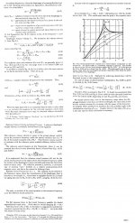
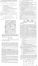
The graph comes from B. Collo's Website. What he is describing is not a passive absorber. It thickness and placement within the enclosure is a very intelligent use of movement within the damping panels. He uses thin foam on the side walls, and the just off center positioning of the damping panels is the key to his successful measurement difference. His enclosure illustration is below.
This is a very intelligent use of the natural resonance points within an enclosure and a method that will work. But it works because you are causing that fiberous tangle or insulation batting in this case to transfer the sound produced inside the enclosure to be converted into heat. The energy inside an enclosre is equal to that produced outside. As your other web reference aptly points out. Both references point to actual changes that have been effected. But it is not the wall lining that is accomplishing the effects. It is the correct placement of the slightly floppy panels. They act as resistive losses. Just as a resister turns a small amount of the electricity across it into heat in a voltage divider so a similar effect takes place interms of change of energy in one state or form into another through the fiberous panel.
I took the liberty of blowing up the graph a bit:

Here is a situation where the impedance plot could tell us quite a bit. If we had an impedance plot of the before and after application of the damping material you could see a few impedance peaks. They would line up pretty much with the peaks in the graphs:
[
The peaks are at approximately 110 hertz and 190 hertz. What is before the peaks are two valleys. These are usually caused by nulls. Basically reflections that meet but one is coming and one is going. When they meet they pretty much disappear. When you can dampen these nulls you will get a little better overall system response. This null in certain frequency wavelengths is caused by the enclosure shape and dimensions. As they are pretty close in frequency you can do a little math and calculated the possible acoustic dimensions within the enclosure. I said that carefully because the calculations cannot perfectly tell you interior dimension. Here is a simple frequency to wavelength calculator:
Wavelength
!/2 and 1/4 wavelengths are what we are interested in. It's quite obvious that the full wavelength is larger than a practical box dimension.
For these acoustical applications there are a few very well thought out products that work very well. Owens Corning in the U.S. has some semi rigid fiberglass panels (707) (Owens Corning Commercial - Fiberglas? 700 Series Insulation) that are perfect for this type of acoustical correction. I don't know if Roxul is available in the U.S. widely but they have a similar panel that they sell in 2' x 4' panels. (ROXUL COMFORTBOARD™ IS)
(Roxul ComfortBoard? IS)
Placement or greatest effects is usually aliitle off center as shown in the diagram. A simple tacked in position with a long enough nail and a hard paper, carboard or cut out from a waste plastic container washer will hold it in place. You want it to be able to move. An you do not want to completely black off or divide your enclosure into sections.
The great thing about audio is that there are so many variables that change the outcome. That is why it is still in large part an art. Not in any way suggesting that it is less of a science. Parts of the art have been well quantified and understood.
Making application of the many possible decisions is the key part.dimensions that dominate the enclosure.
Ben thanks for the well reasoned references.
Nice pictures!
I take it from the pictures that the PVC pipe air transfer conduit is to the left of the doorway. Quite a height up there to gain access!
You will be wanting to put the drivers into your new enclosure after you place your enclosure.
And I liked the view from the top of the bourdon rank. Looks like they were refelted sometime in the past.
@bentoronto
I can't argue with measurements. They stand on their own merrit measuring the conditions at the time of the test.
What I can say is that a measurement graph in absense of the cabinet dimensions and measurement placement postitions etc is hard to discuss.
Just one variable such as the crossover slope being diffeent than the one I used can make a difference.
Another variable is the cone type and diamter. Number of braces and placement within the enclosure. Are they shelf type or full width and length braces? All these factors change the measurement outcome. Was their enclosure a cube? It is the worst scenario for resonances.
What I can say with confidence is that Rod Elliot knows his stuff, and that he is careful to post things he knows are true.
AFter I wrote that little paragraph I thought I owed you a look at the references. They are great examples of how to effect changes within an enclosure.
The graph comes from B. Collo's Website. What he is describing is not a passive absorber. It thickness and placement within the enclosure is a very intelligent use of movement within the damping panels. He uses thin foam on the side walls, and the just off center positioning of the damping panels is the key to his successful measurement difference. His enclosure illustration is below.
This is a very intelligent use of the natural resonance points within an enclosure and a method that will work. But it works because you are causing that fiberous tangle or insulation batting in this case to transfer the sound produced inside the enclosure to be converted into heat. The energy inside an enclosre is equal to that produced outside. As your other web reference aptly points out. Both references point to actual changes that have been effected. But it is not the wall lining that is accomplishing the effects. It is the correct placement of the slightly floppy panels. They act as resistive losses. Just as a resister turns a small amount of the electricity across it into heat in a voltage divider so a similar effect takes place interms of change of energy in one state or form into another through the fiberous panel.
I took the liberty of blowing up the graph a bit:
Here is a situation where the impedance plot could tell us quite a bit. If we had an impedance plot of the before and after application of the damping material you could see a few impedance peaks. They would line up pretty much with the peaks in the graphs:
[
The peaks are at approximately 110 hertz and 190 hertz. What is before the peaks are two valleys. These are usually caused by nulls. Basically reflections that meet but one is coming and one is going. When they meet they pretty much disappear. When you can dampen these nulls you will get a little better overall system response. This null in certain frequency wavelengths is caused by the enclosure shape and dimensions. As they are pretty close in frequency you can do a little math and calculated the possible acoustic dimensions within the enclosure. I said that carefully because the calculations cannot perfectly tell you interior dimension. Here is a simple frequency to wavelength calculator:
Wavelength
!/2 and 1/4 wavelengths are what we are interested in. It's quite obvious that the full wavelength is larger than a practical box dimension.
For these acoustical applications there are a few very well thought out products that work very well. Owens Corning in the U.S. has some semi rigid fiberglass panels (707) (Owens Corning Commercial - Fiberglas? 700 Series Insulation) that are perfect for this type of acoustical correction. I don't know if Roxul is available in the U.S. widely but they have a similar panel that they sell in 2' x 4' panels. (ROXUL COMFORTBOARD™ IS)
(Roxul ComfortBoard? IS)
Placement or greatest effects is usually aliitle off center as shown in the diagram. A simple tacked in position with a long enough nail and a hard paper, carboard or cut out from a waste plastic container washer will hold it in place. You want it to be able to move. An you do not want to completely black off or divide your enclosure into sections.
The great thing about audio is that there are so many variables that change the outcome. That is why it is still in large part an art. Not in any way suggesting that it is less of a science. Parts of the art have been well quantified and understood.
Making application of the many possible decisions is the key part.dimensions that dominate the enclosure.
Ben thanks for the well reasoned references.
Attachments
Hi Bach On,
Thanks for the additional pictures. Those are tight looking shades, just out of general interest, how are they actuated?
Regards,
There is a black box that gets signals from the console (by fiber optics). It sends the signal to a servo motor. There is a rotary gear that pushes and pulls a metal rod for one of the shades. The others are connected and act accordingly. It's pretty responsive. And it is pretty quiet compared to some I've played. I have had the nuts come of the metal rod a couple of times. Finding those suckers on the floor up there is a trip.
The shades are right behind some facade diapason pipes in the choir loft. I'll do a picture another time. There are some obstructions to sound. But the pipes can do it. So maybe the speakers can too. We'll see. And I'll take lots and lots of measurements. And I'll post them for all to see and debate. And some can say, "I told you so." 😀
BTW - Stereo Integrity got my message and confirmed this morning that they would send me to dual 2 ohm driver. If it doesn't do it, maybe I can go for the Dayton later. I'm just hopeful that the triangle corner box and the dual 15" bass box will provide some solid bass. Time will tell whether the combination can do 16 hertz with any authority. Plenty of organs (pipe and electronic) don't play those lowest frequencies well. But I'm cautiously optimistic.
Bach On
Stereo Integrity got my message and confirmed this morning that they would send me to dual 2 ohm driver. If it doesn't do it, maybe I can go for the Dayton later. I'm just hopeful that the triangle corner box and the dual 15" bass box will provide some solid bass. Time will tell whether the combination can do 16 hertz with any authority. Plenty of organs (pipe and electronic) don't play those lowest frequencies well. But I'm cautiously optimistic.
I think you are on the path to a pretty respectable low end. THe SI drivers are better in that they have considerably greater mechanical headroom than the Parts express drivers. About 41mm one way if I remember correctly.
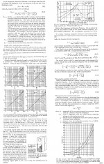
Here is a way to calculate roughly what your loudness will be at a given distance.
Mc Squared System Design Group, Inc. - Javascript Decibel Calculators
Or you can calculate by this rule of thumb:
6 decibels less with each doubling of distance.
One meter simulation at maximum output for your S.I. drivers is 115db.
2 meters would be 109db
4 meters 103db
8 meters 97db
16 meters 91db
.png")
Just above the threshold for hearing out 50 feet way from the source. And that is worst case scenario.
You will have some boundary reinforcement inside. The wavelengths are indeed long. 16.8 hertz is around 64 feet long.
At the console this will be a reall treat.
The great thing about our hearing a way down low is that above the threshold of discernability any increase produces quite a large percieved increase. I'm thinking you will have a system to be very proud of.
I think you are on the path to a pretty respectable low end. THe SI drivers are better in that they have considerably greater mechanical headroom than the Parts express drivers. About 41mm one way if I remember correctly.
Here is a way to calculate roughly what your loudness will be at a given distance.
Mc Squared System Design Group, Inc. - Javascript Decibel Calculators
Or you can calculate by this rule of thumb:
6 decibels less with each doubling of distance.
One meter simulation at maximum output for your S.I. drivers is 115db.
2 meters would be 109db
4 meters 103db
8 meters 97db
16 meters 91db
View attachment 488665
Just above the threshold for hearing out 50 feet way from the source. And that is worst case scenario.
You will have some boundary reinforcement inside. The wavelengths are indeed long. 16.8 hertz is around 64 feet long.
At the console this will be a real treat.
The great thing about our hearing a way down low is that above the threshold of discernability any increase produces quite a large perceived increase. I'm thinking you will have a system to be very proud of.
Both drivers are 18 inchers. The SI HT18 has a 21.5 mm Xmax. The Dayton UM18-22 is 22 mm. So I'd say they are similar. But the power rating on the Dayton is higher (1000 vs. 600 watts RMS). I'd probably need to run the XLS1500 in bridged mode to provide sufficient power for the Dayton driver. I THINK the SI will run from one channel of the amp - that will be a 4 ohm circuit. I want the other channel to power the box with the two 15" drivers - also a 4 ohm circuit. The XLS1500 is rated to provide 525 per channel in 4 ohm mode. So the SI may not get quite enough power. (If not, we may need to get a more powerful amp LATER.) Plus, these cabinets may not be all that efficient. But the HC12s aren't all that efficient either. Maybe I can get the balance tweaked to a good level using the sound engine software.
One good thing about the SPL rule of thumb you mentioned is that people who think the organ is too loud can be advised to sit at the back of the Sanctuary. I do think I'll have the best seat in the room.😉
Bach On
Last edited:
Hi Bach On,
Post #683: "There is a black box that gets signals from the console (by fiber optics). It sends the signal to a servo motor. There is a rotary gear that pushes and pulls a metal rod for one of the shades."
When you're done you'll have an amazing range of technologies coming together in your organ.
Also good to hear that you finally got through to Stereo Integrity. They need to start concentrating on communications, according to all I can find on the internets about them they do a good job with their technology.
Regards,
Both drivers are 18 inchers. The SI HT18 has a 21.5 mm Xmax. The Dayton UM18-22 is 22 mm. So I'd say they are similar. But the power rating on the Dayton is higher (1000 vs. 600 watts RMS). I'd probably need to run the XLS1500 in bridged mode to provide sufficient power for the Dayton driver. I THINK the SI will run from one channel of the amp - that will be a 4 ohm circuit. I want the other channel to power the box with the two 15" drivers - also a 4 ohm circuit. The XLS1500 is rated to provide 525 per channel in 4 ohm mode. So the SI may not get quite enough power. (If not, we may need to get a more powerful amp LATER.) Plus, these cabinets may not be all that efficient. But the HC12s aren't all that efficient either. Maybe I can get the balance tweaked to a good level using the sound engine software.
I mentioned the mechanical limit of the S.I. driver. Not the X-max limit. There are differences.
I just looked at a local installation of one of the drivers you are getting. I think you will do fine. It is a very well made driver. They hooked up a large PA amp to it with 1200 watts per coil and were unable to do any damage to the driver.
Tell the old ladies to move back a couple of pews!
Make sure you push the gas pedals all the way!
Organists know what the gas pedals are!
One good thing about the SPL rule of thumb you mentioned is that people who think the organ is too loud can be advised to sit at the back of the Sanctuary. I do think I'll have the best seat in the room.😉
Bach On
The SPL rule of thumb doesn't work quite so well indoors, as Mark mentioned when he mentioned boundaries.
It's actually likely that the quiet spot might be the middle of the room, around the room boundaries is likely to be the loudest spot, just like in a regular room. This is all freuqency dependent and has to do with modes, standing waves, stuff like that.
They hooked up a large PA amp to it with 1200 watts per coil and were unable to do any damage to the driver.
Yeah but there are also reports of a guy (that knows what he is doing, he's got plenty of experience) blowing a couple of these drivers with a couple of 500 watt amps, below the rated power handling of the drivers. These drivers are NOT intended to accept their limited power rating with a low crest factor signal for any period of time.
I'm pretty sure I could blow one of these with a 300 watt plate amp in a matter of minutes with the right signal.
It is a good driver but the power handling ratings are not conservative like pro driver companies like B&C and 18 Sound.
There's a LOT of hype especially surrounding SI drivers and their power handling and output capabilities, mostly coming from rabid fanboys that have no clue what they are talking about. There's been talk that the SI 24 is equal to 5!!! high excursion 18 inch drivers and it shut down a 7 or 8000 watt amp at a get together. Finally data-bass got some measurements of the driver, and as expected, it was equal to 2 high excursion 18s and had pretty severe power compression setting in at about 1500 watts, which coincides with it's power handling rating. But this is how drivers are sold, get a bunch of people that have no clue what they are doing in a room, give them some gear to play with, hype it up, and it becomes urban legend. SI is the worst company I've ever seen to hype up their drivers in this fashion.
Last edited:
@ Bach On
Damping the panels securely inside the box can make a positive difference to vibration reduction & leakage etc. Stuffing the box is NOT the same though, my any means !
Whatever size/shape box you decide on, to compliment whatever driver/s you install inside it, & tuned to whatever frequency you require, is one thing. When you stuff it with whatever, things change. The more you stuff, the more things change. Plus it depends on what you stuff with & how.
What changes are, the tuning gets lower than designed for, & lower the more you stuff. This naturally affects the frequency response & power limit. This is because the stuffing makes the box acoustically appear bigger than unstuffed. Unless this is factored in @ the design stage, what you expected to get you won't. The alternative is spending hours/days etc with stuffing trial & error methods, installing/removing/testing/listening until you're satisfied !
Plus, unless the stuffing is constrained, it will move in sympathy with air pressure, & also separately affect the tuning etc.
Better to take "note" now, than afterwards, but ulimately it's your gig !
Stapling in a bag pf pillow stuffing (sometimes known as "a pillow") can't have an appreciable influence on the basic resonance but can help with noises higher up, as the previously posted chart shows.
Never found too much difference in organ sound according to row. Sitting around the middle (at least for major stone churches) seems popular with aficionados, I'd say. BTW, the annual Toronto Phantoms of the Organ at Canada's biggest will be Oct 30 at 9 PM... see the Halloween thread. Don't miss it.
Time to think about the short strokes. Cross-bracing in the interior? Mount the heavy driver after the heavy box is wrangled into place*? How to do the wiring if driver is mounted from the front? What's a good binding post? Screen to keep mice out of the port? Little rubber feet to ensure the box sits smartly on an irregular floor and doesn't rattle around? Other practical matters for Bach On?
Ben
*If mounted from the front, will you need to put a brick in the bottom of the box and burn incense to placate the angry Gods of the Sim?
Last edited:
Ben,
I'm doing the bracing on the exterior. I know it isn't as good. But it won't eat up internal volume - which is at a premium for this box. I'm only using minimal stuffing on the hypotenuse boards and the bottom section outside the port area. I may use some poly-fill on the top too, but I'm not sure yet. .
I have closed cell foam to go down on the floor. The bottom of the cabinet will sit on several layers of the foam. It's a pretty level area. so no rubber feet. I have a screw-on terminal block for the wire connection. It will go in the section beside the port on the front face. I'll use #14 stranded wire with crimped spade terminals at the block end.. Then it will be threaded through the box front to the speaker - which will get terminals. The resulting hole will get silicone caulk. I'm using nylon window screen to cover the port exit. Using the same to cover the speaker. I'm probably going to go on and mount the driver. Need to do some basic testing before hauling it up there.
Keep the suggestions coming.
Bach On
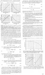
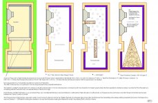
Here are some pictures.
The shades are located behind these non-working pipes. The shades were open and a light was on in the pipe chamber. You can just see some light coming between them.

Here's a shot of the small amount of damping material. Fiberglass was used in the area adjacent to the port. Then I used quilt batting for the area around the speaker and the upper portion of the hypotenuse board. It is held on using spray-on contact adhesive. It seems to be holding fine. The speaker will go in the board on the right. The motor comes down towards the panel on the lower left. The chimney of the port is right behind that panel. The motor extends 9.5 inches. The clearance is pretty close.

I added another board on the speaker face board. It gives a bit more rigidity AND brings the motor forward to reduce the chances it will come in contact with the angled hypotenuse board.

I did the best I could to round over the exit of the port.

Temps are predicted to be 100 today. So I'm going to forego any work on the box today.
I did add exterior supports for the hypotenuse wall last night. No pictures yet.
Bach On
The shades are located behind these non-working pipes. The shades were open and a light was on in the pipe chamber. You can just see some light coming between them.
Here's a shot of the small amount of damping material. Fiberglass was used in the area adjacent to the port. Then I used quilt batting for the area around the speaker and the upper portion of the hypotenuse board. It is held on using spray-on contact adhesive. It seems to be holding fine. The speaker will go in the board on the right. The motor comes down towards the panel on the lower left. The chimney of the port is right behind that panel. The motor extends 9.5 inches. The clearance is pretty close.
I added another board on the speaker face board. It gives a bit more rigidity AND brings the motor forward to reduce the chances it will come in contact with the angled hypotenuse board.
I did the best I could to round over the exit of the port.
Temps are predicted to be 100 today. So I'm going to forego any work on the box today.
I did add exterior supports for the hypotenuse wall last night. No pictures yet.
Bach On
Last edited:
Really nice job!
And holy Particle board Bat Man!
Going to be a heavy enclosure. I've moved around enough of that stuff in my lifetime. 72 lbs a sheet for 5/8". Around 84 for 3/4".
Hope you have eaten your wheaties when you move that box!
And holy Particle board Bat Man!
Going to be a heavy enclosure. I've moved around enough of that stuff in my lifetime. 72 lbs a sheet for 5/8". Around 84 for 3/4".
Hope you have eaten your wheaties when you move that box!
Stapling in a bag pf pillow stuffing (sometimes known as "a pillow") can't have an appreciable influence on the basic resonance but can help with noises higher up, as the previously posted chart shows.
Wrong again. It depends where you put it. A relatively small amount of stuffing can have a huge effect depending on what you do with it. Putting that pillow right in front of the port would really affect the fundamental to a large degree, and if you put that pillow INSIDE the port you could almost (if not completely) kill all resonance coming out of the box through the port. (There would still be sealed box resonance(s) affecting the driver output, but that's something else.)
If there were Gods of the Sim they would be angry that you didn't know any of this stuff when it's so quick and easy to learn by simulating. But really, with all your years of experience you should know this stuff anyway by experience and trial and error. It seems like too much time spent villifying these resonant boxes instead of trying to learn a bit about them has left you in the dark about how they work and what a properly designed example sounds like.
Mark,
I know MDF is the preferred material. And that's what I used for the other cabinet - except for the top and bottom. But I wasn't sure how I was going to do those corners. So I opted for PLAN B. Lowe's had nothing thicker than 5/8 inch. So we have what we have. I tapped all over the two pieces I bought with a hammer listening for problems. But I think it is pretty dense - as am I.
And yes. It is heavy - though it will be in two parts. But the driver alone weighs 37 more pounds. So I'm calling out three or four of the muscle men. But we'll slide it up a ramp we create with an extension ladder. That worked well for the other boxes. I have a two-wheeled dolly to get it to the trailer when I move it to the church.
But nothing else goes to the church or comes out of the speaker chamber until after Bible School. The Bible School Director organized the Contemporary service and heads up the Gestapo for the Praise Team. Anything in her way that looks like it could be for something as traditional as the organ would represent a huge problem for her. I'm just not into any unnecessary dramaterlugical angst. Better to wait out the storm.
Bach On
Really nice job!
Hope you have eaten your wheaties when you move that box!
Remember: this is the South. Folks around here depend on grits. We don't need no stinkin' Wheaties.

Bach On
Nuttin wrong with Particle board says the squirrel. 😀
I actually liked grits the last time I was in the Southern U.S.
😉
I actually liked grits the last time I was in the Southern U.S.
😉
- Status
- Not open for further replies.
- Home
- Loudspeakers
- Subwoofers
- 16Hz for church organ