A few things:
1. A good way to confirm the validity of your approach for simulating designs with high-inductance drivers is to measure the impedance curve and compare it to the sim'd curve. If the changes in the sim'd impedance curve by fiddling with Re and Le don't match the measured impedance curve, then the approach is flawed.
2. HornResp does not include the effect of any losses in its simulations, and the impact of this on the FR and impedance response curve can be quite noticeable depending on the parameters of the alignment. Try using for example software that actually gives the option of adjusting box losses - you'll see the impact at the resonance points, like a vented box's Fb, when you adjust total losses from Ql=3 (lossy) to Ql=infinite. You'll see differences of over 3dB around the resonance points. The impact of this also shows up in the measured impedance curve. It may actually be possible to find the overall Ql by comparing the measured impedance curve to the simulated one, but the ability to do so is way above my level, LOL.
3. Measuring FR can be quite fickle. Using a short sine sweep rather than continuous pink noise and an RTA will give different results for example (and the short sine sweep method is the better one btw, if you want to compare the response against a HornResp sim, as the latter approach can cause Re to rise significantly if done at higher volume, and it will be more significantly impacted by the environment the measurement is being done in). Close-miked measurements will differ from those done at 10M, etc. Then there's the impact of any unknown response anomalies in the mic, the mic amp, etc. as very, VERY few of us have a means of calibrating the FR measuring equipment before using it. That's why I place a lot of emphasis on the impedance response curves to tell me how close I got to the simulated response, and I don't place a lot of emphasis on the FR curve, because if the measured impedance curve matches the sim, then the measured FR (done via short sine sweep with perfect measuring equipment under ideal circumstances, LOL) should be close enough to the sim'd FR as well.
Brian, to address point 1, yes, comparing impedance curves is a great way to confirm accuracy. But as you mention in point 3 "if the measured impedance curve matches the sim, then the measured FR (done via short sine sweep with perfect measuring equipment under ideal circumstances, LOL) should be close enough to the sim'd FR as well."
This goes the other way too, if the simulated box dimensions are the same as the measured box dimensions and the FR curve overlays perfectly, the impedance curve is also going to overlay perfectly.
But as you mention in point 2, there are losses, losses inside the box, losses in the ground, losses in the air, so nothing is every going to overlay perfectly.
To start, let me admit right now my method is not perfect, it can't be, it's so incredibly simple it's actually a miracle that it works at all, and I apply EXACTLY the same tweak to every high inductance driver. But as you can see in the examples I showed it DOES work a lot better than just ignoring the high inductance completely. I'm nowhere near ready to present a doctorate level thesis on this topic, I just found a method that gets really good results and haven't bothered yet to refine the method. But as it is, it's already pretty good.
To go a bit more in depth, I have looked at impedance curves, but not at the level of scrutiny that you do. I'm mainly interested in getting the FR curve right, but as I mentioned, if the FR curve matches the impedance curve will match as well.
Also, as I mentioned, I didn't design or fold ANY of these example boxes that were measured, and it would take a LONG time to reverse engineer the fold to make sure the Hornresp inputs are accurate, something I am not prepared to do right now. At this point I'm happy with the results I'm getting despite putting in the absolute least amount of effort possible. I've been really busy the last few months and this is not high on the priority list, I don't even own a high inductance driver.
It's almost impossible to ignore the impedance curve anyway in this situation because I noted early on when adding Re to simulate power compression that the response humps up right at the impedance peaks. The same things happens with high inductance and it's easy to see. In the data-bass measurements look for the inductance hump and then check the impedance graph. The inductance hump correlates with the impedance peak in a sealed box and you get a rolled off response on both sides of the hump. In a ported box the inductance hump happens at the second (higher) impedance peak, and you also get the same rolled off response on either side of the hump. And same thing with tapped horn and front loaded horn (with slight difference for the multiple impedance peak enclosures).
Sealed boxes are forgiving of high inductance because it's easy enough to just eq the response back to flat so it really doesn't matter all that much. With ported and tapped horn you get a real mess, you don't get much output at tuning, you get a big hump at the second impedance peak, and a rolloff after the impedance peak. In horns (with multiple impedance peaks) the higher impedance peaks are enough to keep the response propped up so it doesn't roll off too much at higher frequencies, but you don't have that in ported boxes so the high frequency response just droops right down like it does in a sealed box. Front loaded horns are much more forgiving, you don't lose the output at tuning like you do with ported or tapped horns, you just get a spikier more overdamped response. This is all confirmed with many sims and measurement correlations.
Basically the high inductance presents as a weaker motor and you need a bigger box to prevent the overdamped response a weaker motor will give.
Now earlier when I mentioned that this is the first time I am aware of that anyone has attempted to simulate high inductance accurately that's not completely true. To explain, there are at least a couple of 3 point complex inductance methods, Leach authored one, and there's at least one more. But to use this method you have to either have the published 3 point inductance t/s parameters or measure them. (Re is one of the added parameters IIRC, so adding Re to simulate inductance can't be too far off the mark.) REW will measure complex inductance so it CAN be measured. But then you need a simulator that will accept these complex inductance parameters, and not many simulators will. Unibox will, but I've been told that it will NOT accept the t/s parameters that REW generates. And since nobody publishes complex inductance parameters you are kind of stuck.
My method works with simple t/s parameters than anyone can measure, the same t/s parameters that manufacturers publish. So anyone can do it with no extra info or complex measurements.
So there are options for simulating high inductance drivers.
1. Ignore it. This will NOT give accurate results, anyone can verify this in 5 minutes. Take a data-bass measurements of both a high and a low inductance driver. Sim the boxes with the box info and measured t/s parameters on the site. The low inductance driver sim WILL match the measurement. The high inductance driver sim WILL NOT match the measurements, not even vaguely close.
2. Use some other method to try to correct for high inductance. A very common approach is to add artificial Le to the sim. This will NOT produce accurate results.
3. Use the 3 point complex inductance t/s parameters. This probably WILL provide accurate results IF you are able to find or measure the complex inductance parameters AND if you are able to find a simulator that will accept them. It's especially hard to find a simulator that will accept complex inductance parameters AND have the ability to sim horns (or other more complex enclosures).
4. Use my method. This WILL provide accurate results. Not perfect obviously but a LOT closer than ignoring the high inductance or using an alternate method to try to fudge a closer correlation. The only better way is to use the complex 3 point inductance parameters, but good luck finding them (or measuring them) and find a simulator that will accept them.
I could say more but that's enough for now.
OP if this is too far OT I am happy to stop talking, but there seems to be interest in this subject. We can take it elsewhere if you like.
Last edited:
Hi JAG,
As this is a high power application of relatively high inductance drivers, I think you are pointing out an important aspect of the design/simulation process.
Regards,
As this is a high power application of relatively high inductance drivers, I think you are pointing out an important aspect of the design/simulation process.
Regards,
Hi mwmkravchenko,
Post #634: "...how are you calculating the length for the triangular vent?"
I usually use the centroid of the triangle for the location of the centerline of the duct, you can see that in the original corner box I posted in Post #552. Then I try to apply soho54's advanced corner method to the transition corner from triangular to rectangular. I feel that the actual effective length has to be determined using measurements of the finished box, but the simulations indicate that this one is very forgiving.
Regards,
The in depth inductance discussion at avsforum starts here, post 224 - HzHorn - Page 8 - AVS | Home Theater Discussions And Reviews
It's a long conversation and you have to go through a lot that isn't related to this topic specifically, but most of the important stuff gets covered by post 310. There's a couple of mentions of inductance past that but no real reason to read further than post 310 or so. This link should answer just about any questions anyone has, if not let me know.
And just for posterity, here's the link to the first time I mentioned this inductance issue, it happened on this very forum in October 2014 - http://www.diyaudio.com/forums/subwoofers/264052-simulating-high-inductance-more-accurately.html
(Note that I picked a bad measurement for the Submaximus front loaded horn in post 1 of this link, not sure why that particular measurement had a drooping top end, but in this thread a few posts ago I showed a much better measurement of that horn without the droopy top end.)
But there's not much there in this link, there was very little interest here probably because this forum doesn't use a lot of high inductance drivers. AVS is all about high excursion drivers, most of which (except TC drivers) have exceptional inductance problems, so this topic gained more traction over there. Ricci even talked about it at the avs link, Ricci is the data-bass guy that did all the measurements and designed the Othorn for those that don't know.
Last edited:
Brian, to address point 1, yes, comparing impedance curves is a great way to confirm accuracy. But as you mention in point 3 "if the measured impedance curve matches the sim, then the measured FR (done via short sine sweep with perfect measuring equipment under ideal circumstances, LOL) should be close enough to the sim'd FR as well."
This goes the other way too, if the simulated box dimensions are the same as the measured box dimensions and the FR curve overlays perfectly, the impedance curve is also going to overlay perfectly.
No it will not. That's in fact the exact opposite of what I was suggesting in my post!
Examples: -
(1) if the amplifier driving the speaker for the FR tests has a boost and cut at lower frequencies, this will be reflected in the FR measurement, but NOT in the impedance curve.
(2) If the FR measurement is done a@1M and then @10M, the FR measurement will be different. The impedance curve however will NOT change if the drive voltage remains the same.
(3) You'd NEVER get an FR curve that matches the Hornresp simulation exactly, because a "lossless" alignments are basically impossible to build.
True enough but -
(1) Who measures with boost and cut? Ideally the signal should be flat, I would hope most people would go to great lengths to make sure of that. At least for FR testing purposes and especially when the goal is to verify accuracy and performance of a design by correlating to a sim.
(2) Most measurements are done at 1m. Data-bass measurements are at 2m (except for the couple he did nearfield close mic'ed and they are clearly labelled as such). Almost no one measures at 10m even if they should. And in the few cases where they do measure at 10m they usually also measure at 1m to correlate to sims. DSL is the only entity I've seen that ONLY measures at 10m. Notice I did mention a few posts back that if you move the mic a few inches you get a slightly different result, this is not true of the impedance curve because the DUT is connected directly so distance is not a factor with impedance measurements (but environment is, so if it was measured in 2 pi you have to sim in 2 pi), while it is a factor with FR measurements. So I am well aware of this issue, but it's really not normally an issue as measurement conditions are usually pretty similar, 2 pi at 1m (or close to 1m).
(3) Yes, and that's what I said. But losses will show up in the impedance curve too.
Anyway, I do agree with you, but under most normal circumstances I stand by what I said, if the box is accurately simulated and measured with a flat signal at 1m (as per usual) the FR and impedance curves should both match reasonably well between measured and simulated. Anyway, all the measurements I'm using were done by Ricci in 2 pi at 2m outdoors with a flat signal except for the Submaximus which was measured by someone else, presumably in 2 pi at 1m outdoors with a flat signal, so in these cases if the FR curve matches reasonably well the impedance curve should too.
Last edited:
True enough but -
(1) Who measures with boost and cut? Ideally the signal should be flat, I would hope most people would go to great lengths to make sure of that. At least for FR testing purposes and especially when the goal is to verify accuracy and performance of a design by correlating to a sim.
What about if the mic itself does not have a flat response? How does one go about verifying the accuracy of the mic before performing a measurement? Or, what about the mic's amp? Or any intervening electronics?
(2) Most measurements are done at 1m.
Measuring any large horn @1M will product inaccurate results. See what TD has to say about that in this thread - http://www.diyaudio.com/forums/subwoofers/140772-correct-way-measure-horn-loudspeaker.html
Thing is, all these measurement techniques have their issues, and trying to simply relate them back to the HornResp sim can be problematic. You may find a "ratch" to curve-fit the measured FR that works for one measurement technique, but not another. That's why I suggest that if you're trying to find an explanation for why the response differs from the sim - an explanation that is NOT dependent on the FR measurement technique, or the inaccuracies introduced by it - then it's best to test out your theories by examining the changes to the impedance curve instead. Increasing Re in a sim for example will have a definite impact on the impedance curve, which can be confirmed via simple measurement.
I'm going to start by saying that I still agree with you in general, what you are saying is true.
And I'm going to continue by saying I really don't care, at least not at this point. I don't have time to reverse engineer all these dozens of designs, confirm their fold accuracy, resim everything and compare impedance curves. I don't even have an impedance curve of the Submaximus flh or the two measurements of Othorn tapped horn with the two different drivers in it.
Back in Sept/Oct I didn't really spend all that much time on this, and since then I've been really busy with other things. I simply don't have time, if you want to do it then be my guest.
The method works to get pretty accurate sims from previously unsimulatable drivers, I'm happy enough with that, and it works every time with every driver. Can it be improved? Absolutely. Am I going to spend any more time on it in the near future? Absolutely not.
You verify the accuracy of the mic by buying a calibrated mic from Cross Spectrum Labs for $95. It's got a built in preamp so mic and amp are both calibrated. Or use measurements from a reputable source like data-bass.
I really don't have the answer for every person in every situation using garbage amps and mics.
ALL the measurements I've used to compare to my sims were from data-bass except the Submaximus horn. It's the only flh measurement with a high inductance driver I could find, so I used it.
That's really all I can do. I can't be responsible for people that can't afford $95 for a powered mic and/or the inclination to make sure their gear is suitable for what they are using it for.
In THAT case I would agree, it would be better to use impedance sweeps, but even then there's no guarantee of accuracy. Commercial woofer testers don't have enough voltage to really get a heavy, large driver moving enough, and if you make your own jig, who is going to verify that it's built properly, the computer sound card plays well with the software, and the soundcard and amp (if used) are all flat?
At some point no matter what you do, you need to be qualified to do it. Garbage in = garbage out.
I know what Danley says. But there's plenty of measurements of horns at 1m, 2m, 10m, and they are going to be fairly close. In the Xoc1 tapped horn thread there's probably measurements at many different distances and they are all fairly close. Besides both Othorn and Submaximus have really small mouths, it's not like I'm using one (or a stack) of Danley's huge large mouth horns here. And in the link you provided even Danley himself says he usually measures at "20 odd feet (in the air) with a mic position at 2 meters usually.", which is pretty close to the procedure used in the measurements I'm using except for the elevated above the ground part.
I'm usually the one pushing for absolute accuracy, but at some point you have to use what you have. I don't have a bunch of big horns to measure so I use what I have, measurements from reliable sources.
And my sims match the measurements pretty well, even though the measurements were all taken at distances of less than 2m, even the horns. And again, I don't have impedance curves for ANY of these horn measurements, so I couldn't use them even if I did have the time to confirm their fold accuracy. And even if I had the time for THAT, there's no way I could possibly confirm the build quality, as you know a single pinpoint air leak or unbraced panel can mess up the impedance curve. As far as I'm concerned, the measurements I have are good enough for what I'm doing with them at this point.
So... while I'd love to do everything absolutely properly I don't have the time or money, and even if I did, comparing a 1m sim to a 10m measurement is going to introduce other problems too. And yes, that's where it would be nice to have an impedance curve instead, but I don't have any measured impedance curves. What I do have is good enough for now.
Again, I agree. For the most part. With stipulations as detailed above, even the impedance curve is not infallible. Some of these have a moving mass of 600 grams, a commercial woofer tester can't really push that, and if you make your own you still have to verify the accuracy of the jig, the amp and the soundcard.
If this was easy, cheap and quick everyone would do it.
As it stands, I'm happy with my results so far.
So to sum it up, I agree with you. The impedance curve is a powerful analytical tool, in many cases even better and more reliable than the FR curve. I just don't have the time or money to do things to a publishable standard right now so I use what I do have.
And I'm going to continue by saying I really don't care, at least not at this point. I don't have time to reverse engineer all these dozens of designs, confirm their fold accuracy, resim everything and compare impedance curves. I don't even have an impedance curve of the Submaximus flh or the two measurements of Othorn tapped horn with the two different drivers in it.
Back in Sept/Oct I didn't really spend all that much time on this, and since then I've been really busy with other things. I simply don't have time, if you want to do it then be my guest.
The method works to get pretty accurate sims from previously unsimulatable drivers, I'm happy enough with that, and it works every time with every driver. Can it be improved? Absolutely. Am I going to spend any more time on it in the near future? Absolutely not.
What about if the mic itself does not have a flat response? How does one go about verifying the accuracy of the mic before performing a measurement? Or, what about the mic's amp? Or any intervening electronics?
You verify the accuracy of the mic by buying a calibrated mic from Cross Spectrum Labs for $95. It's got a built in preamp so mic and amp are both calibrated. Or use measurements from a reputable source like data-bass.
I really don't have the answer for every person in every situation using garbage amps and mics.
ALL the measurements I've used to compare to my sims were from data-bass except the Submaximus horn. It's the only flh measurement with a high inductance driver I could find, so I used it.
That's really all I can do. I can't be responsible for people that can't afford $95 for a powered mic and/or the inclination to make sure their gear is suitable for what they are using it for.
In THAT case I would agree, it would be better to use impedance sweeps, but even then there's no guarantee of accuracy. Commercial woofer testers don't have enough voltage to really get a heavy, large driver moving enough, and if you make your own jig, who is going to verify that it's built properly, the computer sound card plays well with the software, and the soundcard and amp (if used) are all flat?
At some point no matter what you do, you need to be qualified to do it. Garbage in = garbage out.
Measuring any large horn @1M will product inaccurate results. See what TD has to say about that in this thread - http://www.diyaudio.com/forums/subwoofers/140772-correct-way-measure-horn-loudspeaker.html
I know what Danley says. But there's plenty of measurements of horns at 1m, 2m, 10m, and they are going to be fairly close. In the Xoc1 tapped horn thread there's probably measurements at many different distances and they are all fairly close. Besides both Othorn and Submaximus have really small mouths, it's not like I'm using one (or a stack) of Danley's huge large mouth horns here. And in the link you provided even Danley himself says he usually measures at "20 odd feet (in the air) with a mic position at 2 meters usually.", which is pretty close to the procedure used in the measurements I'm using except for the elevated above the ground part.
I'm usually the one pushing for absolute accuracy, but at some point you have to use what you have. I don't have a bunch of big horns to measure so I use what I have, measurements from reliable sources.
And my sims match the measurements pretty well, even though the measurements were all taken at distances of less than 2m, even the horns. And again, I don't have impedance curves for ANY of these horn measurements, so I couldn't use them even if I did have the time to confirm their fold accuracy. And even if I had the time for THAT, there's no way I could possibly confirm the build quality, as you know a single pinpoint air leak or unbraced panel can mess up the impedance curve. As far as I'm concerned, the measurements I have are good enough for what I'm doing with them at this point.
So... while I'd love to do everything absolutely properly I don't have the time or money, and even if I did, comparing a 1m sim to a 10m measurement is going to introduce other problems too. And yes, that's where it would be nice to have an impedance curve instead, but I don't have any measured impedance curves. What I do have is good enough for now.
Thing is, all these measurement techniques have their issues, and trying to simply relate them back to the HornResp sim can be problematic. You may find a "ratch" to curve-fit the measured FR that works for one measurement technique, but not another. That's why I suggest that if you're trying to find an explanation for why the response differs from the sim - an explanation that is NOT dependent on the FR measurement technique, or the inaccuracies introduced by it - then it's best to test out your theories by examining the changes to the impedance curve instead. Increasing Re in a sim for example will have a definite impact on the impedance curve, which can be confirmed via simple measurement.
Again, I agree. For the most part. With stipulations as detailed above, even the impedance curve is not infallible. Some of these have a moving mass of 600 grams, a commercial woofer tester can't really push that, and if you make your own you still have to verify the accuracy of the jig, the amp and the soundcard.
If this was easy, cheap and quick everyone would do it.
As it stands, I'm happy with my results so far.
So to sum it up, I agree with you. The impedance curve is a powerful analytical tool, in many cases even better and more reliable than the FR curve. I just don't have the time or money to do things to a publishable standard right now so I use what I do have.
Last edited:
Hi Bach On,
Post #632: "...The triangular upright bends and connects to the bottom rectangular area. The opening at the front is 9.25 inches wide x 4.25 inches high. But the front face is 24 inches wide. So there is an area running parallel to the floor that is NOT part of the port. It is roughly half the width of the driver. It is separated from the port by an upright under the middle of the driver (ending at the hypotenuse wall). I'm guessing that the area should be open into the area directly right behind the speaker?..."
Correct. We need every little bit of volume we can get. The port consists of two sections, the vertical triangular section, and the horizontal rectangular section exiting at the bottom right below the driver. Looking back at the drawing from May 13th, Post #565: on the right hand side are a number of cross-sectional areas that I used to calculate the internal volume(s), the one that says: S_bot=64.304in^2... that is the area for that bottom section of the box. The next one up in the drawing is the area above the top board of the bottom rectangular section of the port located behind the driver, and the one on the top is for the upper box section above the port.
Use the brace @ the inlet of the port inside the box, and round over all inlet and exit edges. I matters.
Don't worry about the length of the port too much, as the Hornresp screen plot from Post #631 shows, even an increase of ~5" port length will not derail the system. This may be a terrible thing to say as some builders seem to fret about minute differences in length, but in this particular case it is really not a big deal (now, don't take that to mean you can just leave out the whole triangular section, or something like that 🙂.)
Regards,
OK, I've got the bottom portion of the cabinet mostly done. Getting that port system right took some doing, but I believe I have it mostly right. I'll do the silicone caulking this evening. You've suggested rounding off the exit edges of the horizontal port. I'm going to see if I can do that.
But there is a right angle where the rear of the horizontal (rectangular) section enters the triangular portion of the port. I can't see any good (mechanical) way to round off this angle. I'm hopeful that it won't matter that much.
Now - on the subject of damping material: my limited understanding is that damping can reduce resonance, but at the cost of SPL. Too, damping seems needed mostly for parallel walls. The triangle shape produces few of those. So I was thinking of using some spray-on adhesive and a light amount of poly-foam insulation on the outer wall of the hypotenuse - but not in the port. By light - I mean maybe a 1/4 inch thick covering. I also thought it might be good to have the same treatment on the very top board. (the interior of the cover). After the adhesive has dried, I'd use an air gun to remove any particles that weren't firmly attached. Some have suggested I wouldn't need any damping material. Since this is your design, what do you think?
Triangular walls don't lend themselves to easy interior bracing. Too, as you've pointed out - I need every bit of interior volume for this cabinet. The four foot high hypotenuse wall is the largest panel. I was thinking of using exterior bracing for that wall. I mean a couple of 1x4 boards running up and down secured with wood glue and screws. Then I'd glue and screw a couple of smaller flat rectangular panels between them to reduce thrumming. (I considered a second full layer of the hypotenuse board, but that would add substantially to the weight.) I'd do the same thing to the hypotenuse portion for the smaller upper box, but without the flat panel pieces.
I'll use 1x4 boards around the joint to create a "socket" of sorts so the upper boards will fit into the correct position. These will be secured with PL adhesive and screws when everything is finally mated. We have company coming for a visit, so my wife has a long list of "honey do" projects for me. But the top portion of the cabinet should go together pretty quickly.
I'll try to post a few pictures of the bottom section after I've got the caulking done. Then I can attach the triangular bottom. I've got to get a new round-over bit for my router. I figured some paint or varnish after this is done might help. I'm favoring painting the exterior of the box.
I just wish I had the driver so I could start wiring the system up. I'm considering contacting Stereo Integrity and asking that they change my order to the 2 ohm version of the HT18. I can connect the dual voice coils in parallel and come up with a 4 ohm circuit. The Crown XLS1500 should handle that fine.
Well, that's the latest news.
Bach On
P.S. Mark Anderson just called me. The new 16 MIDI channel Artisan sound engines won't ship until July. He has now relocated to Lumberton, North Carolina. That puts him right on the Interstate 95 - North-South corridor for the East Coast. He'll come install it when the console work is completed.
Last edited:
Hi Bach On,
Post #650: "... Some have suggested I wouldn't need any damping material. Since this is your design, what do you think?"
I think you are doing the right thing in using at least a little open pore foam glued to the inside. It would not hurt to place a layer of fiberglass batting into the bottom. "Some" are correct, if you are looking only at the performance of a subwoofer.
Post #650: "...change my order to the 2 ohm version of the HT18. I can connect the dual voice coils in parallel and come up with a 4 ohm circuit..."
From the SI website:
"- HT18 Dual 2 ohm voice coils
Re 3.5 ohms"
That means to me, that they have both coils in series for their T/S specification (if they are "Dual 2 ohm"), and that they are Re=1.75 Ohm ea. , also, if you connect them in parallel you have to divide 1.75 by 2, and get Re=0.875 Ohm. It's easy to get parallel and series mixed up. I'm withholding what I think about their documentation. From what I hear their product is OK.
Good to hear that you are making progress.
Gotta run.
Regards,
Don't know about the SoHo method of calculating an out of round port.
Basically it might be a smart thing to be able to tune the port in this configuration. Unless the forgiveness mentioned by Oliver is such that close enough works quite easily.
Anthony, I think you are running into the never ending excitement of using different software packages to do a simulation.
The most complete free package I know of and recommend is UniBox. It factors in almost all of the known losses.
Few of the other packages do this extensive of a simulation.
WinISD has some flaws, as does Bagby's software.
Davids never claimed to factor in the losses. But is quite accurate on the many simulations versus measurements that I have performed.
As Brian states the best comparison is in the impedance peaks simulated versus measured. Once they start lining up you are doing well.
Inductance by itself has not the effects you are attributing to it. (Yoda moment)
Different mathematical simulations are your source of the differences.
What are your favorite sim programs?
The most complete free package I know of and recommend is UniBox. It factors in almost all of the known losses.
But it won't simulate any complex enclosures and the complex inductance parameters it will accept are not generated by any t/s measuring software I know of and these complex inductance parameters are not published anywhere for any drivers.
In other words, Unibox is completely useless as far as I'm concerned.
Inductance by itself has not the effects you are attributing to it. (Yoda moment)
Different mathematical simulations are your source of the differences.
Yes it does. The ONLY way I would agree with this statement is if by "different mathematical simulations" you mean Hornresp can't accept or use 3 point complex inductance t/s parameters. Because this is very clearly an inductance issue, and inductance very clearly does have the effects I'm attributing to it. It's right there in the measurements for anyone to see, dozens of high quality measurements.
I challenge you to take ANY measurement of a high inductance driver on data-bass.com and try to match it's measured response to a sim. Use the measured t/s parameters and the listed box info on data-bass for the measured driver.
I'll save you some time here. You can't do it. Not with any simulator. Not Unibox (unless maybe you can find 3 point complex inductance parameters for the driver), not any other program.
BUT if you take any LOW inductance driver from data-bass.com and sim it with his measured t/s and box info you WILL get an accurate sim that matches the measurement.
This is NOT different mathematical simulations causing a difference, low inductance driver sims match measurements, high inductance sims don't. Every time. With every simulator. This is very clearly an inductance issue.
This inductance issue is actually pretty well known too, everybody knows (at least everybody that his simulated and measured a high inductance driver) that they don't sim right.
This is very clearly an inductance issue, Yoda.
Before you dismiss this again I want to see you sim a high inductance driver and have it match a data-bass measurement of a driver with Le:Re ratio higher than 1:1. Try the RE XXX driver. Good luck with that.
Leach came up with the 3 point complex inductance t/s parameters and authored a big paper on the subject for a reason. That reason is that inductance does things that cannot be simulated or estimated with the regular common t/s parameters. And Leach isn't the only one, there's at least two different sets of 3 point complex inductance t/s parameter definitions.
Ricci also commented on my inductance correction method (he's the data-bass guy). He said he does something very similar to force his sims to correspond to measurements of high inductance drivers. Read the links I posted.
Just to be really clear here, this is only an issue with drivers with very high Le:Re ratio, 1:1 or higher. Even as high as .75:1 don't seem to be affected much (if at all), but at 1:1 things go really screwy. I've seen the work you do, I've seen the drivers you use, I seriously doubt you have ever even looked critically at a measurement of a very high inductance driver much less measured one or compared sims to measurements. This is a very well known issue with ultra high excursion ultra high inductance drivers. It's not at all an issue with the type of drivers you are used to.
What are your favorite sim programs?
Hornresp, Akabak, MJK's worksheets, TL.app. Each for different things. I almost never use anything else for enclosure simulation. And the latter two I use very rarely. 99 percent of the time I use Hornresp exclusively, less than one percent of the time I use Akabak, and a tiny fraction of the time I use the other two.
Last edited:
Just to be really clear here, this is only an issue with drivers with very high Le:Re ratio, 1:1 or higher. Even as high as .75:1 don't seem to be affected much (if at all), but at 1:1 things go really screwy. I've seen the work you do, I've seen the drivers you use, I seriously doubt you have ever even looked critically at a measurement of a very high inductance driver much less measured one or compared sims to measurements. This is a very well known issue with ultra high excursion ultra high inductance drivers. It's not at all an issue with the type of drivers you are used to.
I don't remember you being at my side when I do measurements.
Or when I work on very long excursion drivers.
I have a driver in the prototype stage right now that has a 42mm X-max.
And I worked on a few of the Funk Audio drivers as well.
Yes they are different drivers, I have used XBL on some of my design work. Bit not on all of it.
And I have a measurement package that tests the advanced inductance parameters and can accurately model the parameters.
I just don't write a whole lot about it on diyaudio. No point really.
I'll post some pics later.

.jpg")

And I have a measurement package that tests the advanced inductance parameters and can accurately model the parameters.
And that right there is the key. Just like I said. You are measuring frequency dependent resistance and reactance. These are completely different t/s parameters and this issue is NOT "different mathematical simulations" as you said. These different t/s parameters are there to accomodate changes made by inductance, so this is an inductance issue, and inductance does have the attributes I am attributing to it.
So why are you not using your fancy package to accurately model the parameters in horn simulations? Why do you use Hornresp? I suspect your program can't model horns.
So again we're back where we started. I challenge you to take any measurement of a high inductance driver from data-bass and simulate it accurately with any simulation software that is capable of also simulating complex enclosures like horns.
If you can't do that and my method can, my method has value.
You can say inductance doesn't do what I say it does, but if you can't sim a simple sealed box properly without your fancy software and complex inductance t/s parameters, you would be wrong.
Hi Y'all,
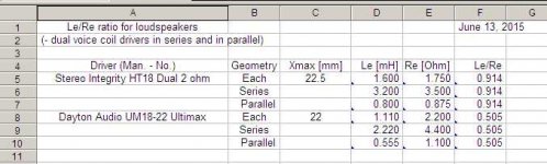
So, JAG's analysis would mean that the Dayton would be the better driver for this box, as it has a much lower Le/Re ratio?
Le/Re ratio for loudspeakers:
(- dual voice coil drivers in series and in parallel)
Driver (Man. - No.) Geometry Xmax [mm] Le [mH] Re [Ohm] Le/Re
Stereo Integrity HT18 Dual 2 ohm Each 22.5 1.600 1.750 0.914
Series 3.200 3.500 0.914
Parallel 0.800 0.875 0.914
Dayton Audio UM18-22 Ultimax Each 22 1.110 2.200 0.505
Series 2.220 4.400 0.505
Parallel 0.555 1.100 0.505
Regards,
Attachments
Last edited:
Is it getting time to bring structure to this parade of thoughts about coil inductance?
Does the model break down for larger inductances.... even though the actual reactance at frequencies of interest (below, say 80 Hz) is quite small? Problems with the model?
Or are the measurements flawed (as measurements always are to some degree)?
One thing I know for sure, you don't play with a "black box" sim as if it was a video game. You don't say, "Gosh, if I just twiddle the inductance by goosing up the Re (instead of Le...) then gosh, the curves look better to my eyes..." That's more like guesswork than science.
If there's a discrepancy for larger inductance coils (which no doubt have other anomalies in those drivers, eh), it needs to be explained. Not played with by twiddling this and that parameter till the curve feels better.
Ben
Last edited:
Hi Y'all,
So, JAG's analysis would mean that the Dayton would be the better driver for this box, as it has a much lower Le/Re ratio?
The Dayton is a better driver in general, there's measurements of both drivers at data-bass. But it's also more expensive IIRC. And I haven't simulated it in ported boxes but it doesn't look good at all in tapped horns.
Last edited:
Is it getting time to bring structure to this parade of thoughts about coil inductance?
Does the model break down for larger inductances.... even though the actual reactance at frequencies of interest (below, say 80 Hz) is quite small? Problems with the model?
Or are the measurements flawed (as measurements always are to some degree)?
The measurements are not flawed, the only thing keeping the data-bass guy from being a full on pro is he's not being paid (as far as I know). And how do you explain the fact that ALL the low inductance drivers measure the same as they sim but ALL the high inductance drivers don't? Do you think he screwed up ALL the high inductance driver measurements, and ONLY the high inductance driver measurements?
My method has worked well for ALL high inductance drivers I've tried, Le:Re ratios from 1:1 all the way up to 2:1. And it doesn't get much higher than 2:1.
One thing I know for sure, you don't play with a "black box" sim as if it was a video game. You don't say, "Gosh, if I just twiddle the inductance by goosing up the Re (instead of Le...) then gosh, the curves look better to my eyes..." That's more like guesswork than science.
If there's a discrepancy for larger inductance coils (which no doubt have other anomalies in those drivers, eh), it needs to be explained. Not played with by twiddling this and that parameter till the curve feels better.
Ben
Ben, you don't play with any sims ever, how are you qualified to tell guesswork from science? I'm STILL waiting on an answer to the simple technical question I asked you a dozen times in this thread. There's no guesswork here at all. I've done the work, done the sims, and the method works. For every high inductance driver in every enclosure. People that REALLY know what they are doing have verified that my method works and is valid, people like the data-bass guy that did the measurements in the first place.
Look at kravchenko's picture of the output of his program a couple posts up. The complex inductance t/s parameters have a frequency dependent resistance and frequency dependent reactance parameter. Using those complex inductance parameters in a simulator that can accept them is pretty close to the same thing I am doing by forcing a simulator that can't accept them to consider their effect.
What other anomalies do you think these high inductance drivers have? This is purely an inductance effect. ALL the low inductance driver sims match measurements, ALL the high inductance driver measurements are not even vaguely close. What else do you think is causing this?
My method is NOT random twiddling with the sim parameters. It's a very well defined, very simple tweak that is applied to ALL high inductance drivers, and it works 100 percent of the time. What else do you really want?
Having said that, there is room for a bit of refinement in my method, but as you can see from the data I posted here and the data I linked to, it's already very good. Did you not notice the sims match the measurements? Between the data I posted here and the linked data there's got to be a dozen sim/measurement comparisons of sealed boxes, tapped horns and front loaded horns, and I've got a lot more too. How much more proof do you need that the method works?
Last edited:
- Status
- Not open for further replies.
- Home
- Loudspeakers
- Subwoofers
- 16Hz for church organ