Calling all the speaker pros out there. I've been waiting well over a month for the Stereo Integrity HT18" speaker. I've written them and received no response. It is now June 9th, and the website still says they will ship sometime in May. SI farmed the job out to Sundown Audio. They look like they are behind on a lot of things. I just don't have a good feeling about this.
HT18 18″ Subwoofer | Stereo Integrity
I was advised by several here that this speaker had good "bones" for a budget model - though SI didn't post the exact specs for the 4 ohm version I wanted. I'm getting restless - (maybe just impatient that they won't even give me a firm ETA). I've looked for an alternative 18 inch driver to go in that triangular box I'm building.
Here's a link to the Dayton Audio UM18-22 -
Dayton Audio UM18-22 18" Ultimax DVC Subwoofer 2 ohms Per Coil
It's just over a hundred books more, but it looks like it also has good bones, though it has dual 2 ohm voice coils. I really thought dual 4 ohm might be better for our needs. Though I'm not certain how crucial that would be. The flip side is that I could cancel my order for the 4 ohm HT18 and just order the 2 ohm version. The specs for that driver are listed. Power ratings are substantially higher on the Dayton. Would our Crown XLS1500 provide enough power to adequately power this driver without straining and distortion?
Have others used either of these drivers? How would you think the Dayton compares with the SI HT18 in a large ported enclosure for reproducing sounds down around 16 Hz.? Is the difference worth $104.90 more?
Bach On
Last edited:
Hi Bach On,
Looking at a simulation of the UM 18-22 in the corner box @ 1kW (the rated Prms) the driver is still below Xmax (~ 18mm @ 26Hz). With both coils in series you are looking @ Re=4.36 Ohm, so the Crown XLS1500 would have to be used in bridged mode, Pmax=1.55kW into 4 Ohm. That should work very well, and leave you some power reserves.
Regards,
We've had some spurious sounds in our PA system. I've been working with one of the "I'll get it done" guys to troubleshoot the issue, but it's taken many months to get a handle on where it's been coming from. Finally substituted one of my own mics for the pulpit mic, and that's solved it, though the actual cause is still murky. We're thinking that 30 year old XLR connectors may be part of it, plus that 30 year old condenser mic (my mic is dynamic, so doesn't require phantom power).
Our organist has been making noises about the age of our Rogers organ, too, though I've assured him we can keep the amps and speaker drivers working for quite some time yet.
If it sounds like pop corn popping or other non repeating humming it is probably the power supply electrolytic capacitors. If your amplifier is 30 years old they definietley have dried out. They are faily cheap to buy and pretty easy to swap out.
Here is a comparison of equal power input into the two drivers.
Black is the Stereo Integrity. Grey is the Dayton Audio. Simulated with one watt into 8 ohms or 2.83 volts.

There is 3.6 decibels difference at 100 hertz. That is noticeable by nearly everyone.
Black is the Stereo Integrity. Grey is the Dayton Audio. Simulated with one watt into 8 ohms or 2.83 volts.
There is 3.6 decibels difference at 100 hertz. That is noticeable by nearly everyone.
More corn for the grist mill
Here is one more possibility. Considerably cheaper. And when you do the actual power in versus SPL attained calculations it is rather impressive.

Putting on a consulting hat I would make two cases for choosing one set of drivers over the other.
Broad band the Stereo Integrity driver will get you a pretty good output level watt for watt. It is the black line. The cheap Dayton PA 18 inch is a very interesting contender. Almost 4 times as efficient up in the 4 foot and 8 foot stop regions. And pretty close in the 16 foot stop regions to the Stereo Integrity drivers in black. As for 32 foot stops they are almost equal in output.
The cheaper drivers with have considerably more slam. This is due to the efficiency that they have over the other choices. I know this because of doing quite a bit of subwoofer driver design and system testing. The more efficienct drivers have an edge in terms of headroom. And music is made with dynamics. Even in the low end.

Stereo Integrity

Stereo Integrity

Dayton Audio PA460*8 18" Pro Woofer

Dayton Audio PA460*8 18" Pro Woofer
There is a slight difference in the price between the two.
Here is one more possibility. Considerably cheaper. And when you do the actual power in versus SPL attained calculations it is rather impressive.
Putting on a consulting hat I would make two cases for choosing one set of drivers over the other.
Broad band the Stereo Integrity driver will get you a pretty good output level watt for watt. It is the black line. The cheap Dayton PA 18 inch is a very interesting contender. Almost 4 times as efficient up in the 4 foot and 8 foot stop regions. And pretty close in the 16 foot stop regions to the Stereo Integrity drivers in black. As for 32 foot stops they are almost equal in output.
The cheaper drivers with have considerably more slam. This is due to the efficiency that they have over the other choices. I know this because of doing quite a bit of subwoofer driver design and system testing. The more efficienct drivers have an edge in terms of headroom. And music is made with dynamics. Even in the low end.
Stereo Integrity
Stereo Integrity
Dayton Audio PA460*8 18" Pro Woofer
Dayton Audio PA460*8 18" Pro Woofer
There is a slight difference in the price between the two.
Mark, we're kind of off-topic. I've proved definitely the pops are not from the 4 year old amp by replacing the amp with one from my own system. Pops same. Replace pulpit mic, pops gone.
Calling all the speaker pros out there. I've been waiting well over a month for the Stereo Integrity HT18" speaker. I've written them and received no response. It is now June 9th, and the website still says they will ship sometime in May. SI farmed the job out to Sundown Audio. They look like they are behind on a lot of things. I just don't have a good feeling about this.
This is one of the many reasons I don't like this company at all. But the driver is the current value leader and he isn't a thief so I wouldn't worry, just relax and wait. Or cancel your order, it's up to you. SI and Sundown are very close, if anything I'd trust Sundown a lot more, so if they are doing the work I'd imagine it will get done right. Anyway, I thought Sundown was just processing their orders or something. I don't think there's anything to worry about unless you are in a rush to get it.
Here is a comparison of equal power input into the two drivers.
Black is the Stereo Integrity. Grey is the Dayton Audio. Simulated with one watt into 8 ohms or 2.83 volts.
View attachment 487588
There is 3.6 decibels difference at 100 hertz. That is noticeable by nearly everyone.
This comparison means nothing. The SI is a high inductance driver and it won't measure the same as it sims. Check data-bass for measurements, then sim the box they used and see how they don't match at all. You get a big inductance hump at the impedance peak (the higher impedance peak in a ported box) and then a pretty severe rolloff on both ends. Which means there's going to be a lot more difference than 3.6 db at 100 hz (assuming the Dayton is not also very high inductance), and other very significant differences everywhere else too since the SI sim is just plain wrong because it doesn't sim right due to the inductance. PM me if you want to know how to sim high inductance drivers properly.
I haven't really looked into the Dayton too much yet as far as inductance and performance but it's also measured on data-bass so you can easily compare the two.
Here is one more possibility. Considerably cheaper. And when you do the actual power in versus SPL attained calculations it is rather impressive.
Rather impressive for PA duty (but only considering the price - there are much better PA drivers if you want to pay more). Almost completely useless for 16 hz, like all PA drivers.
Last edited:
Thanks to both of you. I'll check those out. Mark, the thing that concerns me about the cheaper Dayton driver is the limited Xmax.
TB46 - I'm currently working on the cabinet. I'm to the point of contemplating how best to install the port. The upright board right behind the speaker was shown as being 18.5 inches tall. This creates what I'll call the triangular chimney of the port. Thus, it is part of the total area of the port. What would be the effect of this board being 4 or 5 inches taller? Does increasing the port area raise or lower the tuning of the box? I understand that this would reduce the free volume of the cabinet.
As you suggested, I'm building it in two sections. The driver and port will go in the larger lower section. It is 48 inches high. Then the top will sit on top of that. I'll used 1x4 boards around the joint to secure everything. I figured to use PL Construction Adhesive where the boards of the two sections meet. That should glue and seal the joints.
Bach On
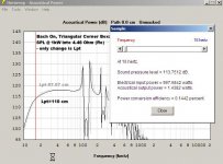
Hi Bach On,
The length (height) of that board determines the length of the port. The longer the port, the lower the tuning frequency (all else being equal). I'll attach a simulation showing the old length (97.07cm) and a new length (110cm), there is very little difference, the shorter length looks like it would be preferrable (see attachement).
The cross-sectional area of the port in that location (the back corner) is the triangular area that one is looking down at; this then turns into the rectangular port that comes out the front.
A quick check of the impact the inductance might make is to double Le, and compare the SPL curves. The UM 18-22 does have a rated Le of 3.09, going to 6.09 looks OK (some, but very little change).
Use PL and whatever clamping/screwing you can. A little extra time spend here is a good thing. Remember, you are building a prototype, and the world is watching. 🙂
Regards,
Attachments
Hi Bach On,
The length (height) of that board determines the length of the port. The longer the port, the lower the tuning frequency (all else being equal). I'll attach a simulation showing the old length (97.07cm) and a new length (110cm), there is very little difference, the shorter length looks like it would be preferrable (see attachement).
The cross-sectional area of the port in that location (the back corner) is the triangular area that one is looking down at; this then turns into the rectangular port that comes out the front.
A quick check of the impact the inductance might make is to double Le, and compare the SPL curves. The UM 18-22 does have a rated Le of 3.09, going to 6.09 looks OK (some, but very little change).
Use PL and whatever clamping/screwing you can. A little extra time spend here is a good thing. Remember, you are building a prototype, and the world is watching. 🙂
Regards,
So, longer port = lower tuning. But what are the trade-offs for that?
And I've got to assume that there is a limit for what (good and bad) a longer port can do.
Yes. I know I'm consulting with the creator of the prototype. So I don't want to screw it up I'll try to make you proud. I do have one question about the rectangular port area. It's rather difficult to tell from the excellent drawing you posted. The triangular upright bends and connects to the bottom rectangular area. The opening at the front is 9.25 inches wide x 4.25 inches high. But the front face is 24 inches wide. So there is an area running parallel to the floor that is NOT part of the port. It is roughly half the width of the driver. It is separated from the port by an upright under the middle of the driver (ending at the hypotenuse wall). I'm guessing that the area should be open into the area directly right behind the speaker? It's hard to describe, but I can sketch it out if it would help..
One of these days I plan to actually learn to do these sims myself. I've just got a lot or irons heating right now. Thanks to all of you for your kind assistance.
JAG - Do you see any downside if I went for the 2 ohm version of the HT18 vs. the 4 ohm version? I believe the 2 or 4 ohm numbers are nominal. But fewer ohms means the amp can push more voltage down the line because of decreased resistance. Does using a speaker with a lower ohm rating produce negative side-effects?.
Out of curiosity, this speaker will only receive one channel of the bass line. (That part is programed in the sound engine.) So nothing would be left out of that channel if only one voice coil was connected. What are the advantages in this scenario of using both voice coils vs. just one voice coil?
Bach On
Hi Bach On,
Post #632: "...The triangular upright bends and connects to the bottom rectangular area. The opening at the front is 9.25 inches wide x 4.25 inches high. But the front face is 24 inches wide. So there is an area running parallel to the floor that is NOT part of the port. It is roughly half the width of the driver. It is separated from the port by an upright under the middle of the driver (ending at the hypotenuse wall). I'm guessing that the area should be open into the area directly right behind the speaker?..."
Correct. We need every little bit of volume we can get. The port consists of two sections, the vertical triangular section, and the horizontal rectangular section exiting at the bottom right below the driver. Looking back at the drawing from May 13th, Post #565: on the right hand side are a number of cross-sectional areas that I used to calculate the internal volume(s), the one that says: S_bot=64.304in^2... that is the area for that bottom section of the box. The next one up in the drawing is the area above the top board of the bottom rectangular section of the port located behind the driver, and the one on the top is for the upper box section above the port.
Use the brace @ the inlet of the port inside the box, and round over all inlet and exit edges. I matters.
Don't worry about the length of the port too much, as the Hornresp screen plot from Post #631 shows, even an increase of ~5" port length will not derail the system. This may be a terrible thing to say as some builders seem to fret about minute differences in length, but in this particular case it is really not a big deal (now, don't take that to mean you can just leave out the whole triangular section, or something like that 🙂.)
Regards,
A quick check of the impact the inductance might make is to double Le, and compare the SPL curves. The UM 18-22 does have a rated Le of 3.09, going to 6.09 looks OK (some, but very little change).
That does not work at all to simulate the effects of high inductance. Adding more artificial inductance to the sim will not give an accurate result. I'll send you a PM later when I get some time.
I've run at least a couple dozen sims to verify my inductance correction method, all compared to high quality measurements, mostly done by Josh Ricci and most (but not all of them) are measurements on the data-bass site. So I've got a pile of sims of high inductance drivers in sealed boxes, one or two in ported boxes, a couple of tapped horn examples and a front loaded horn. My inductance correction method works very well to correlate sims to measurements regardless of enclosure type. Doubling Le in the sim won't even get in you in the right ballpark.
JAG - Do you see any downside if I went for the 2 ohm version of the HT18 vs. the 4 ohm version? I believe the 2 or 4 ohm numbers are nominal. But fewer ohms means the amp can push more voltage down the line because of decreased resistance. Does using a speaker with a lower ohm rating produce negative side-effects?.
If the amp is rated to drive it you can do it. I wouldn't worry about side effects.
The only reason I would hesitate to push an amp to it's low impedance limits is if my budget was unlimited (it's always going to be happier pushing less, but how much do you want to pay for that?) or if I was planning to later add another driver in parallel, which would eventually push the amp to it's limits when the other driver was added.
If the amp isn't rated for the lower impedance load definitely don't do it.
When you decrease the impedance of the driver you need to increase the current driving the speaker. The reason is simple. Almost all amplifiers are voltage sources. They try to send a consistent voltage to the driver with the change in the drivers impedance versus frequency.
The problem is that amplifiers are driven with transisters that have current limits. They cannot usually double the current into a load that is one half that of 8 ohm to 4 ohm or 4 ohm to 2 ohm.
So the percieved increase in power usually hits a bit of a no return for change at the 4 ohm level.
Add in the situation of where this subwoofer will be operating the impedance of the drivers is considerably higher than the nominal rating in the first place.

At different pitches the impedance seen by the amplifier varies quite a bit.
16 hertz 8.54 ohms
32 hertz 32.1 ohms
64 hertz 8 ohms
The problem is that amplifiers are driven with transisters that have current limits. They cannot usually double the current into a load that is one half that of 8 ohm to 4 ohm or 4 ohm to 2 ohm.
So the percieved increase in power usually hits a bit of a no return for change at the 4 ohm level.
Add in the situation of where this subwoofer will be operating the impedance of the drivers is considerably higher than the nominal rating in the first place.
At different pitches the impedance seen by the amplifier varies quite a bit.
16 hertz 8.54 ohms
32 hertz 32.1 ohms
64 hertz 8 ohms
Just a guy
You have me wondering what you are discussing in terms of inductance changing the results of the simulation.
Care to explain?
I can think of a few things that the motor inductance can change. But maybe you are on to something that I am unaware of.
You have me wondering what you are discussing in terms of inductance changing the results of the simulation.
Care to explain?
I can think of a few things that the motor inductance can change. But maybe you are on to something that I am unaware of.
Just a guy
You have me wondering what you are discussing in terms of inductance changing the results of the simulation.
Care to explain?
I can think of a few things that the motor inductance can change. But maybe you are on to something that I am unaware of.

I could write a (short) book on the topic but I have to work really early in the morning so I only have time for a quick explanation right now.
For the last 3 years or so while looking through data-bass measurements I was noticing that the measurements of high inductance drivers (drivers with Le:Re ratio of 1:1 or more) didn't match sims. At all. Not even close. He provides measured t/s parameters and box details so you can sim yourself, and I did. And I recognized the response curve shape difference. It looked exactly like what happens when you add additional Re to the sim, I know this because I'm always adding Re to simulate the effect of power compression in high power sims.
So I finally got around to testing this in sims about a year ago and it worked really well. I added Re and then added more power to compensate for the losses the additional Re caused. And I got very accurate results, not perfect but very close to the measurements. Every time. With every high inductance driver in every enclosure. Dozens of sims, dozens of measurements, my inductance compensation method worked. Sealed box, ported box, tapped horn, front loaded horn, it doesn't matter, my correction method worked on everything with every high inductance driver that I compared to Josh Ricci's high quality measurements.
Here's some quick examples.
First, for some backup data, here's the UXL in a sealed box measured by Ricci. In the sim I've simulated the same driver in the same box with (red line) and without (blue line) my inductance correction method. The uncorrected response isn't even vaguely close to the measurement, the corrected response is pretty close.
An externally hosted image should be here but it was not working when we last tested it.
Next up is UXL in Submaximus front loaded horn. Here's the sim vs the measurement. Green is measured response. Again red line in sim is corrected, blue is uncorrected.
An externally hosted image should be here but it was not working when we last tested it.
Next up is two different high inductance drivers in Ricci's Othorn tapped horn. I ran the numbers with Ricci's measured t/s for the UXL and Sundown ZV3.
Each sim has regular results in light grey and my inductance compensated results in dark black under Ricci's measurement. IIRC these measurements were taken nearfield indoors so he explained that's why the higher frequencies droops a bit. There's more info on these measurements in the data-bass forum but I don't have time to find and reread it.
Disregard actual spl levels, they mean nothing here.
First pic is UXL, second is ZV3.
An externally hosted image should be here but it was not working when we last tested it.
An externally hosted image should be here but it was not working when we last tested it.
And that's just a few examples, I've got many many more. My method works every time.
Then a few months ago there was a lengthy discussion on my method at avsforum, and member LTD02 suggested that high inductance "detunes" the motor (really just reducing motor strength), and he was able to show results similar to mine by just reducing the Bl, which has the added advantage of not needing to add more power to compensate for added Re power losses which needs to be done with my method. I haven't had time to vet his method yet, comparing sims using his method against dozens of measurements to make sure it's accurate every time with every driver in every enclosure, but at a glance his method seems to work fine too, and it's a bit easier to do than mine, and has a couple other advantages as well.
There's a lot more to this that I don't have time to explain right now, but for now the pictures above should be enough. They tell the story. Regular sims don't work for high inductance drivers. My method works very well. Not 100 percent accurate but very close. LTD02's method has a few advantages and the potential to possibly be even more accurate than my method. As far as I know no one has ever even attempted to simulate high inductance drivers accurately before this.
I can provide more explanation, links, more pictures, more examples, whatever you like if you are interested, but this is really only tangentially on topic for this thread per se. We should discuss it elsewhere, which is why I suggested PM.
Last edited:
BTW Ben, are you paying attention here? Add these 4 examples to the dozens I've already shown you of sims matching real world measurements.
And in this case, these are high inductance drivers too (aka impossible to simulate accurately) and I came up with a way to do it. Before you nitpick that the sims don't match the measurements EXACTLY remember there are a few reasons for that. Move the mic a few inches and you get something a bit different. Also I didn't design or fold any of these boxes so there may be errors in translation from sim to plans (almost no one is 100 percent accurate when translating their sim to the finished product and I used the designer's Hornresp inputs to sim all the horns but did not verify their accuracy to the plans). And I just had the net volume of the sealed box example and guessed at it's dimensions. And the tapped horn measurements were done indoors nearfield so won't be the same as data-bass's regular outdoor 2m measurements. And probably most important, my correction method is remarkably simple, it's the same exact tweak applied to every single high inductance driver so it can't possibly be completely accurate without a bit of refinement because not all high inductance drivers are exactly the same.
And as I've mentioned at least dozens of times sims are never COMPLETELY accurate, there are dozens of things that sims can't possibly consider.
But having said all that, the sims are remarkably accurate, especially considering the fact that these drivers are basically impossible to sim accurately before I came up with an inductance correction method, no?
At this point I've shown you dozens of sims that match real world measurements and you continue to claim sims are not valid. Not sure what else I can do... Feel free to completely ignore these examples as you have ignored the piles of previous evidence I've shown you...
Last edited:
- Status
- Not open for further replies.
- Home
- Loudspeakers
- Subwoofers
- 16Hz for church organ