Yep. You pegged the dimensions correctly. I didn't pay real close attention at the time. I can now see that this protrusion is going to stick out and into the path of the doorway. It won't be bad, but it will be easy to hit the surround without some protection.
I am going to put on the nylon screen to cover the driver. It won't be seen, but somebody could hit the thing. Better safe than sorry.
Bach On
I am going to put on the nylon screen to cover the driver. It won't be seen, but somebody could hit the thing. Better safe than sorry.
Bach On
If this is an organ swell box which is sealed all around except for the blinds, might be playing into something less that 2-pi and bass might benefit even if it violates the sim assumptions being used. Anybody know acoustics want to comment? Or organs?
Ben
Ben
Last edited:
True only for the near field. The only reinforcement will be below 32 hertz. The frequency wavelength at 32 hertz is roughly 32 feet. If I'm remembering the dimensions correctly the auditorium is 75 by 100.
If it is less, the point were reflections start to help will move higher up.
If it is less, the point were reflections start to help will move higher up.
True only for the near field. The only reinforcement will be below 32 hertz. The frequency wavelength at 32 hertz is roughly 32 feet. If I'm remembering the dimensions correctly the auditorium is 75 by 100.
If it is less, the point were reflections start to help will move higher up.
True enough of the sanctuary.
I was thinking of pressurizing inside the smallish swell box (with the blinds open) which I assume is reasonably sealed outside of the blinds (which also form a kind of port!). In any case, doesn't look to me like the proverbial 2-pi of a sim.
When an organist uses the blinds, there's a level change of maybe 15 dB, I'd guess. So the boxes have to be reasonably sealed.
Ben
Last edited:
To lossy of an enclosure.
Sure cries out for a quick test run with REW before sequestering in the swell box. If only to satisfy the modelers who, I hope, are keen to see how well their modeling works and for others to learn from Bach On's great efforts.
If the organ loft proves to be deficient as a sub location, might be possible to camouflage a sub box elsewhere esp in a propitious corner. Shape of box is of little importance, so it can be re-shaped to minimize the visual aspect.
My own expectation is that the new box can provide a welcome boost of solid bass in the 40-90 Hz region where the music lives but hardly an impact below 32 Hz. Nearly all big pipes I've ever heard from electric organs are the partials from which the perception of bass fndamentals (that aren't really there) are constructed in the brain. A quick peak at the shoddy woofers used would give anybody on this forum the same impression.
Which is why the expert development of the sub in this thread holds promise of something better.
Ben
Last edited:
After the infamous Bible School is over and after this cabinet is actually assembled, I'm pretty certain I'll just have to run some measurements on the output of this box - and probably both the bass boxes together. .
Ben may be correct that these two boxes may not provide enough SPL below 32 Hertz to be effective out in the Sanctuary. But I did see some measurable activity at 16 Hertz from the single ported box with the two 15 inch Dayton woofers. The recommendations from Stereo Integrity for the HT18 calls for a ported enclosure of 5-6 cubic feet for 20 Hertz. The cabinet I'm currently building should have an internal volume just under 10 cubic feet. So I'm reasonably confident that this new box will do 16 Hertz, not just play partials and overtones. Will the two boxes be enough? I can only hope so - at least in the short-term.
I haven't mentioned this before, but the choir loft and the platform with the pulpit and two chairs is raised above the main Sanctuary floor about 30 inches. There is a sunken pit where the organ console has been placed. The choir sits in a semi-circle around the console. Beneath the floor where the choir sits is an enclosed area that probably has something like 40-50 cubic feet of volume, perhaps substantially more. This totally enclosed area might be a candidate position for an infinite baffle setup if it is needed. But I'm trying (at least initially) to have all the sound sources behind the shades.
Bach On
Last edited:
I wonder, if the chamber is actually completely sealed, if there's not a way to sim the whole mess together in HR..
Sent from my SM-G920T using Tapatalk
Sent from my SM-G920T using Tapatalk
I wonder, if the chamber is actually completely sealed, if there's not a way to sim the whole mess together in HR..
Sent from my SM-G920T using Tapatalk
That's why I think the step-by-step method is to document the new speaker in a known or baseline setting (both near and far traces)* and then to carry on to the next step.
Otherwise, diagnosis under a wholly new setting in the pipe loft will be hard to interpret.
Guess I am just Aristotelian and empiricist while the sim adherents are Platonists.
Ben
*and fine-tune as the sim'ers might recommend, in the event the speaker isn't perfectly perfect the first time
Last edited:
Yeah, it's a bit beyond that step now that I'm thinking about it, lol.
Sent from my SM-G920T using Tapatalk
Sent from my SM-G920T using Tapatalk
Hi DrDyna,
Post #728: "...a way to sim the whole mess together in HR..."
It should be possible in AkAbak. If you've got the time, we've got..... 🙂.
Regards,
Post #728: "...a way to sim the whole mess together in HR..."
It should be possible in AkAbak. If you've got the time, we've got..... 🙂.
Regards,
There are four openings into the chamber. There is a door into the pipe chamber and another one into the speaker chamber. The pipe door has been sealed pretty well with weather stripping. None has been added to the speaker door yet, though it will. There is also a 1x2 foot port for a fan that runs when the organ is off to keep moisture at bay. The only other opening is the shades. By design, the shades open up when the organ is turned off. That allows air to be sucked through the chamber by the fan in the rear.
The walls of the pipe chamber are plaster over lathe. The same is true of the ceiling. The floor is hardwood. The speaker chamber has a plywood floor. The short side walls are plaster over lathe. The back wall is sheetrock and 2x4s at 16 inch on center. We're going to add fiberglass between the 2x4s and a layer of foam insulation with an aluminum foil back towards the speakers. I'm hopeful the foil will reflect a few more frequencies. I dunno.
I'd estimate that the pipe chamber is 16 feet in length - from door to wall. The height is probably 7 feet. And the distance from the rear wall to the wall with the shades is probably just under 5 feet. Pipes run down both sides of the long walls. Additional pipes sit on a platform about three feet high that sits over the wind chest that keeps the air pressure to the pipes even. There is an L shaped bend that juts off at the end away from the doors. More pipes are located in this area. I'd estimate the floor area of the pipe chamber is 120 square feet. But that is a real guess. I've not put a tape measure to it.
The speaker chamber joins the pipe chamber through an opening that is probably 6x7 feet. I'd guess that the shades are 7x7 feet.
I'm not familiar with how to run sims using HR, but my guess is that it would be a challenge to sim the chamber with any reliability. But some of you guys amaze me with what you can do.
Good to hear from you DrD.
Bach On
Last edited:
Think of how a pipe organ works. Air is blown through the foot of the pipes and the air rushes either through the pipe to produce a vibration.
The swell enclosure cannot be sealed. It has to let the air out when the pipes are in play.
I don't know the organs specifications. Nor the number of stops under expression control in the swell box. But the quantity of air that has to be released is not small.
The swell enclosure cannot be sealed. It has to let the air out when the pipes are in play.
I don't know the organs specifications. Nor the number of stops under expression control in the swell box. But the quantity of air that has to be released is not small.
Add one pi to the sim? Two pi's?Think of how a pipe organ works. Air is blown through the foot of the pipes and the air rushes either through the pipe to produce a vibration.
The swell enclosure cannot be sealed. It has to let the air out when the pipes are in play.
I don't know the organs specifications. Nor the number of stops under expression control in the swell box. But the quantity of air that has to be released is not small.
What do the sim'ers think will be the revised output?
(Don't ask me, I always stick subs in corners.)
B.
Last edited:
It seriously depends on the construction of the walls of the building and how far away they are.
The organ loft will close to a wall. If it is of conventional stick framing and sheathing it is essentially invisible below 30 hertz. If there is brick we are much better shape. Stone likewise. You need mass to reflect the sound waves.
Definitely inside this building we are 2 Pi at the worst. And that type of loading will increase to 1 and even .5 as the frequency drops.
You need an architectural acoustics simulator to really get you in the correct ballpark.
I have some. But I'd need some firm numbers on the room dimensions and shape of the ceiling as well as the wall construction type.
Then I'll take a stab at it.
All this free consulting is starting to add up!
Kidding. Would not be offering if I was not interested in seeing this work out well.
I can't claim to understand these things, but it now seems to me the speaker is kind of just hanging in space at low frequencies, acoustically speaking, as Bach On describes the organ/swellbox loft. Wouldn't that be considered 4 pi? That might be OK for a pipe but what about a cone?Definitely inside this building we are 2 Pi at the worst. And that type of loading will increase to 1 and even .5 as the frequency drops.
How does HR handle it? I mentioned "pie" a day or two ago but didn't seem to arouse any interest and so I thought my point wasn't important.
B.
Last edited:
Pipe, cone. Same poop different pile. They both have to pressurize the air at a given frequency rate to produce sound. So if a pipe in an organ can make a sufficient SPL a cone moving the same amount of air at the same frequency will be the same SPL.
Now for some pi:
MMM. Pie...

The yellow parts are the reflective surfaces. None for 4Pi. One reflective surface like the ground for 2Pi. Two reflective surfaces for 1Pi. And three for 0.5Pi.
Now I'm hungry. All this pie and nothing to eat....
😡
Now for some pi:
MMM. Pie...

The yellow parts are the reflective surfaces. None for 4Pi. One reflective surface like the ground for 2Pi. Two reflective surfaces for 1Pi. And three for 0.5Pi.
Now I'm hungry. All this pie and nothing to eat....
😡
We have had very hot temps lately. And it stayed hot and muggy into the night. But I went out late last night and built the top portion of the new triangular bass cabinet.
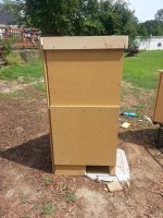
Here's the front view of the lower portion. The height is a nominal 49 inches, counting the bottom. You'll notice the front face has a second layer of board where the speaker will be positioned. This is partly to re-enforce the face. It also serves to bring the driver forward a bit so the motor doesn't come in contact with what I've called the hypotenuse board.

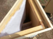
I put boards to create a flange around the top of the vertical boards. The plan is to put the larger box in place in the corner of the speaker chamber. Then I'll apply PL Construction adhesive to the top boards around the perimeter. Here's a rather fuzzy shot showing the area.

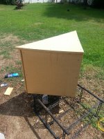
This is a shot of the shorter top box. It is roughly 25 inches in height. It will be placed in the "socket" created by the flange boards on the lower portion of the cabinet. I'd estimate it weighs roughly 50 to 60 pounds. I figure it will butt up against the boards in the previous photo. The PL adhesive should hold it in place AND provide some degree of seal for air leaks. I've already tried dry fitting it. And it seems to match up very well with the lower section. I figure two guys can lift it and drop it into the slot without much trouble.

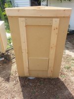
I may be wrong in my thinking, but I've used exterior supports rather than interior supports. More Internal Volume was my goal. So the largest board will get external re-enforcement like you see in this photo. I'll do the same on the upper hypotenuse board. I'll also put quilt batting on the interior of the hypotenuse board of the upper section like I did on the lower section. I have some fiberglass batting. I was thinking of stapling some to the interior of the top.

My next task is to make the cut-out for the speaker. Once that hole is done, I need to put in a rounded over internal brace for the board right behind the speaker. I'll add boards around the eventual location of the speaker to protect the protruding rubber surround. It is right at 1 and half inches. Then I'll paint the whole thing with brown paint. After the paint dries, I'll do the wiring block and install the driver with bolts. Finally, nylon screen wire will be stretched and either stapled or otherwise attached to protect the speaker.
I think it will then be time to take it to the church. I'm guessing we're looking at something over 200 pounds when it is all put together. It seems sturdy. And I'm hopeful I'm sealing all the leaks with silicone caulk as I go. My concern is vibrations. But I figure I'll identify any in testing and try to eliminate any.
This cabinet looks like it will have an internal volume of just under 10 cubic feet. And it will fit well in the corner for which it was designed. Many thanks to Oliver for his plan. I'm cautiously optimistic that it will produce some low pedal sounds to go with the newly ported 13 cubic foot cabinet with the two 15 inch Dayton drivers. Keep your fingers crossed!!! 😕
Bach On
Here's the front view of the lower portion. The height is a nominal 49 inches, counting the bottom. You'll notice the front face has a second layer of board where the speaker will be positioned. This is partly to re-enforce the face. It also serves to bring the driver forward a bit so the motor doesn't come in contact with what I've called the hypotenuse board.

I put boards to create a flange around the top of the vertical boards. The plan is to put the larger box in place in the corner of the speaker chamber. Then I'll apply PL Construction adhesive to the top boards around the perimeter. Here's a rather fuzzy shot showing the area.

This is a shot of the shorter top box. It is roughly 25 inches in height. It will be placed in the "socket" created by the flange boards on the lower portion of the cabinet. I'd estimate it weighs roughly 50 to 60 pounds. I figure it will butt up against the boards in the previous photo. The PL adhesive should hold it in place AND provide some degree of seal for air leaks. I've already tried dry fitting it. And it seems to match up very well with the lower section. I figure two guys can lift it and drop it into the slot without much trouble.

I may be wrong in my thinking, but I've used exterior supports rather than interior supports. More Internal Volume was my goal. So the largest board will get external re-enforcement like you see in this photo. I'll do the same on the upper hypotenuse board. I'll also put quilt batting on the interior of the hypotenuse board of the upper section like I did on the lower section. I have some fiberglass batting. I was thinking of stapling some to the interior of the top.

My next task is to make the cut-out for the speaker. Once that hole is done, I need to put in a rounded over internal brace for the board right behind the speaker. I'll add boards around the eventual location of the speaker to protect the protruding rubber surround. It is right at 1 and half inches. Then I'll paint the whole thing with brown paint. After the paint dries, I'll do the wiring block and install the driver with bolts. Finally, nylon screen wire will be stretched and either stapled or otherwise attached to protect the speaker.
I think it will then be time to take it to the church. I'm guessing we're looking at something over 200 pounds when it is all put together. It seems sturdy. And I'm hopeful I'm sealing all the leaks with silicone caulk as I go. My concern is vibrations. But I figure I'll identify any in testing and try to eliminate any.
This cabinet looks like it will have an internal volume of just under 10 cubic feet. And it will fit well in the corner for which it was designed. Many thanks to Oliver for his plan. I'm cautiously optimistic that it will produce some low pedal sounds to go with the newly ported 13 cubic foot cabinet with the two 15 inch Dayton drivers. Keep your fingers crossed!!! 😕
Bach On
Nice!
Bracing inside or outside is better than no bracing at all.
You are looking to stiffen the panel and raise it's resonance higher up in frequency. And you have accomplished that for sure.
Your two part box idea is great. And the PL Premium will indeed seal the two together both air tight and otherwise as long as you have a good continuous bead of the evil stuff. Wear gloves unless you like wearing PL for a few days.
- Status
- Not open for further replies.
- Home
- Loudspeakers
- Subwoofers
- 16Hz for church organ