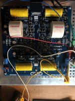
No, send a PM to vicnic and request one. He sells them fully assembled and tested. They look like this:
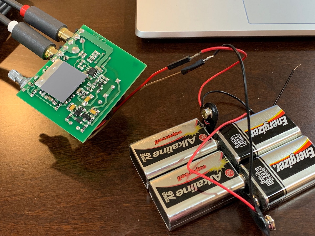
I use 4x 9v batteries in series to get clean low noise 36v supply.
I also have the Akitika and it’s nice too. Cones with a case but you have to assemble it (very easy to build).
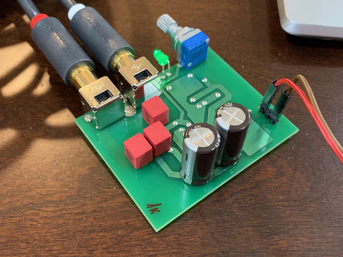
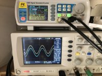
1 kHz Oscillator
I use 4x 9v batteries in series to get clean low noise 36v supply.
I also have the Akitika and it’s nice too. Cones with a case but you have to assemble it (very easy to build).
1 kHz Oscillator
Last edited:
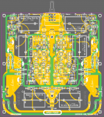
SoundsGreat, perhaps this PCB file will be useful to you.
Thank you very much for the same🙂, Really appreciate it.
If you could also please take a look at my draft & post your valuable feedback it'll be great.
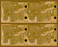
SoundsGreat, your PCB looks good. I always try to make the protection on a separate board, place it on the output terminals. Since any inductor has the property of emitting and interfering with neighboring parts, I also put this coil on the protection circuit board.
Attachments
Thank you very much for the same🙂, Really appreciate it.
If you could also please take a look at my draft & post your valuable feedback it'll be great.
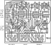
Sreekanth, your layout looks very nice and compact. Did not check for correctness etc - will
leave that to the experts.
However, I am wondering how you would plan to mount the R33s - would they float a bit ?
In your layout, the R33s pass over the pads of the output transistors.
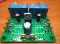
Here is a stereo protection board which was posted on a Russian
forum - it is designed to be mounted on the speaker jacks.
Warning Note: not tested by me, but seems to be a proven design.
forum - it is designed to be mounted on the speaker jacks.
Warning Note: not tested by me, but seems to be a proven design.
Attachments
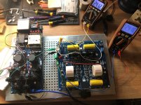
Preamp P30ZF final connection and test
P30zf powered with the SALAS Ultra Bib PSU and APEX ON/OFF switch with standby Led. 24V 100mA for the two channels
P30zf powered with the SALAS Ultra Bib PSU and APEX ON/OFF switch with standby Led. 24V 100mA for the two channels
Attachments
Last edited:
If understood correctly, 47k and 470R are for 12V and 12V relay (?).
Yes. Vcc=24V - 120k, Vcc=12V - 47k. Accordingly, a relay with a coil for 24V or 12V.
Last edited:
SoundsGreat, your PCB looks good. I always try to make the protection on a separate board, place it on the output terminals. Since any inductor has the property of emitting and interfering with neighboring parts, I also put this coil on the protection circuit board.
Thanks again, Yes seems like good idea. But for me in this case might not workout as Am planning to use this for subwoofer plateamp,So don't have the terminals and such.
Sreekanth, your layout looks very nice and compact. Did not check for correctness etc - will
leave that to the experts.
However, I am wondering how you would plan to mount the R33s - would they float a bit ?
In your layout, the R33s pass over the pads of the output transistors.
Report Post Reply With Quote
If you could check that'd be great too as no expert has stepped in to do it till now.
As with the resistors, They are given little oversized footprint just to make sure I can accommodate the big resistors (some of the local ones are) so shouldn't matter much but in case if it does then yes lift it a bit and solder.
Thanks again to you, yurik, and others who bothered to take time to respond.
Hello friends!
I need the gerber file of the power supply board for APEX PREAMP P30ZF
I have one for the preamplifier, but I don't have one for its power supply.
Please help urgently.
I need the gerber file of the power supply board for APEX PREAMP P30ZF
I have one for the preamplifier, but I don't have one for its power supply.
Please help urgently.
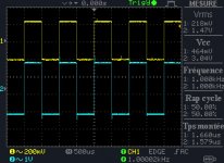
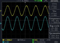
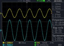
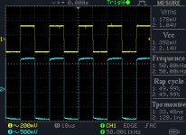
P30ZF left channel test
Same result than the Right channel..Prefect.
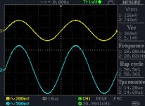
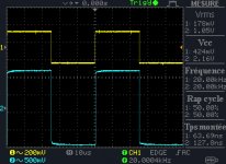
Now time to plug all the boards for the reel test. The last Picture with channel R and L 150 mV 1kz Input, Vol Pot Maximum
Same result than the Right channel..Prefect.
Now time to plug all the boards for the reel test. The last Picture with channel R and L 150 mV 1kz Input, Vol Pot Maximum
Attachments
Hello friends!
I need the gerber file of the power supply board for APEX PREAMP P30ZF
I have one for the preamplifier, but I don't have one for its power supply.
Please help urgently.
Go to A-class Preamp PSU
GERBER files fo P30ZF
Hicoco, Please GERBER files fo P30ZF.
Same result than the Right channel..Prefect.
Now time to plug all the boards for the reel test. The last Picture with channel R and L 150 mV 1kz Input, Vol Pot Maximum
Hicoco, Please GERBER files fo P30ZF.
i do not have Lay6, i will post the gerbers when i will be done with all tests
PDF for termic transfer?
I also ask for the gerber file.
Thank you very much
Thank you very much
- Home
- Amplifiers
- Solid State
- 100W Ultimate Fidelity Amplifier