Is this a clone that you are "ok" with? Would you recommend that an interested hobbyist try this kit to compare with their other projects (such as MX50X2 and MA9S2)?
Due to the very high interest in this thread I thought this "100W Ultimate Fidelity Amplifier" might be a suitable next project for me to explore.
Or do you recommend a different starting point instead of this kit? (Maybe it is or is not a good clone, and/or maybe you have another design that you would suggest instead?)
The FH9 was the hexfet mod I made based on latFET FX8. I have since improved it with better layout by JPS64, 2oz copper with via stitching and ultimate upgraded parts (yet still budget conscious) to enable best sound and 100w operation with +/-52v rails called the FH9HVX. Boards are available if you are interested. It is a superb sounding amp. I am listening to it on my TL speakers as I type. If this was the last amp I had, I would not be unhappy.
I even made the Griddle Amp with it ($10 heatsink - can’t beat that price):
Last edited:

Guess no one read or bothered to respond, So I'll ask again.
Please can someone share the files for the two pairs version of AX14P like this one (With added protection circuit)
100W Ultimate Fidelity Amplifier
Or even this one which already has it, Although the above with protection would be perfect as Am planning a multi channel amp and the smaller boards makes it perfect candidate for the same.
100W Ultimate Fidelity Amplifier
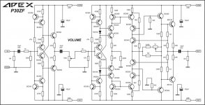
P30ZF Right channel test
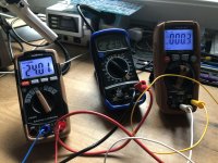
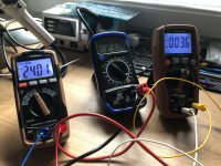
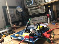
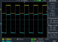
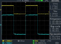
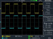
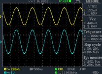
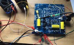
Here are the first tests of the right channel of the P30ZF. Unfortunately I don't have the tools to measure THD.
I will work on the left channel now.
Please let me know your thought.
Couple of Question,
What is the 1K trimmer for, now it is adjusted 50%.
I have an offset oscillating between 0,3mV Dc and 3,6mV Dc at the output. Is that ok?
Attachments
-
 IMG_3065.jpg983.4 KB · Views: 755
 -
 IMG_3066.jpg974.7 KB · Views: 727
 -
 IMG_3068.jpg913.8 KB · Views: 685
 -
 DS0007.jpg38.3 KB · Views: 134
 -
 DS0005.jpg95.1 KB · Views: 135
 -
 DS0004.jpg112.6 KB · Views: 127
 -
 DS0003.jpg87.5 KB · Views: 128
 -
 DS0001.jpg98.2 KB · Views: 138
 -
 DS0000.jpg108.6 KB · Views: 188
 -
 IMG_3067.jpg1,023.8 KB · Views: 673
Guess no one read or bothered to respond, So I'll ask again.
Please can someone share the files for the two pairs version of AX14P like this one (With added protection circuit)
100W Ultimate Fidelity Amplifier
Or even this one which already has it, Although the above with protection would be perfect as Am planning a multi channel amp and the smaller boards makes it perfect candidate for the same.
100W Ultimate Fidelity Amplifier
i did answer before.
alex mm make one and tested.
100W Ultimate Fidelity Amplifier
for protection use f100 or fx100 apexaudio psu. it have protection on it...
Here are the first tests of the right channel of the P30ZF. Unfortunately I don't have the tools to measure THD.
If you have a sound card or USB audio interface, you can measure distortion easily. Download free copy of REW.
Howto - Distortion Measurements with REW
I'm trying to set the bias on my board but the most it will move is from 1.2mv to 1.3
Double check r16 and r17 value. Also, try jumper at r23 [edit - noticed you already have ground wire to input]. One more thing, mount Q10 directly to output transistor, using wire leads to connect to board. I didn't do this at first and bias was fluctuating. Thanks prasi for spotting that on my build.
Attachments

Last edited:
Somehow mine has 10mV and idle current via Q14 and output at 0.10~0.15mA with no setting.
its working ok and nothing is getting hot, should i get worried?🙄 been up for the past 20min
Looking good with one exception. Mount Q10 to output transistor. See above, post 13148.
Here are the first tests of the right channel of the P30ZF. Unfortunately I don't have the tools to measure THD.
I will work on the left channel now.
Please let me know your thought.
Couple of Question,
What is the 1K trimmer for, now it is adjusted 50%.
I have an offset oscillating between 0,3mV Dc and 3,6mV Dc at the output. Is that ok?
With 1k trimmer set THD, offset is ok.
i did answer before.
alex mm make one and tested.
100W Ultimate Fidelity Amplifier
for protection use f100 or fx100 apexaudio psu. it have protection on it...
Am sorry I didn't notice your reply to my post.
100W Ultimate Fidelity Amplifier
Secondly I have already the AX14p with inbuilt Protection ages ago but now want a more compact version of the same which is what I have asked above. Don't want to have too many PCB's and too much wiring. Hence would prefer a all in one layout (if PSU caps could be added then even better).Am not good with pcb design and such hence requesting here else would've done it myself & shared it here.
Thanks xrk, i just download it , but i don't figure out how to connect the preamp output to my MacIf you have a sound card or USB audio interface, you can measure distortion easily. Download free copy of REW.
Howto - Distortion Measurements with REW
Thanks, what is the value and the best way to add a Balance PotWith 1k trimmer set THD, offset is ok.
If you have a sound card or USB audio interface, you can measure distortion easily. Download free copy of REW.
Howto - Distortion Measurements with REW
If anyone on diyaudio has successfully setup REW with a Sound Blaster Audigy 2 ZS on Windows 10 please let me know. I have tried and tried and searched and searched and I can not get rid of what looks like a feedback path when I calibrate. It is a known problem with a few Creative Labs products but I have not been able to fix it with the Audigy 2 ZS on Windows 10.
I can calibrate with no problem using the motherboard's built-in soundchip but the distortion is too high to make meaningful amplifier measurements hence my attempts to use the much cleaner Audigy 2 ZS that I have sitting around.
Am not good with pcb design and such hence requesting here else would've done it myself & shared it here.
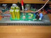
I assembled an AX-14 on pcb, which I ordered from this link: Apex AX-14 - Share Project - PCBWay
. The pcb fit well with 7cm heatsinks. The diodes and capacitors of the power supply are located on the amplifier board.
Attachments
New Draft AX-14P
Thank you for your reply but there are few issues with that, This version does not have protection which is what I mainly need and also the caps are too small Am looking at using 2 of 22,000mfd or so and SMD Parts etc to name few due to which I cannot go with it, I had already checked it out,But thanks nonetheless for your valuable response.
But even if I overlook the above biggest problem is,Currently there's tension between India and China that's causing all sorts of hell and due to this nothing from China is being allowed into India,So ordering it from the above is ruled out, That is the reason for me to ask for Sprint or Gerber files so that I can get the PCB done locally.
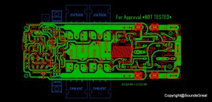
Anyways since no one bothered to respond I did what I could best and here's the result (might be poorest by other's standard but still).
I request people who are good at this to kindly take a look at the addition and either correct it or let me know what to do.
I assembled an AX-14 on pcb, which I ordered from this link: Apex AX-14 - Share Project - PCBWay
. The pcb fit well with 7cm heatsinks. The diodes and capacitors of the power supply are located on the amplifier board.
Thank you for your reply but there are few issues with that, This version does not have protection which is what I mainly need and also the caps are too small Am looking at using 2 of 22,000mfd or so and SMD Parts etc to name few due to which I cannot go with it, I had already checked it out,But thanks nonetheless for your valuable response.
But even if I overlook the above biggest problem is,Currently there's tension between India and China that's causing all sorts of hell and due to this nothing from China is being allowed into India,So ordering it from the above is ruled out, That is the reason for me to ask for Sprint or Gerber files so that I can get the PCB done locally.
Anyways since no one bothered to respond I did what I could best and here's the result (might be poorest by other's standard but still).
I request people who are good at this to kindly take a look at the addition and either correct it or let me know what to do.
Attachments
Last edited:
Thanks for this new draft of AX-14P.
You might get more help if you also attach the schematics to it.
Have a nice day.
You might get more help if you also attach the schematics to it.
Have a nice day.
Thanks for this new draft of AX-14P.
You might get more help if you also attach the schematics to it
No need to thank,Hardly anything I did here. The Schematics is the original AX-14P with LED's added (as per the desertstorm's layout)
Hope at least now people respond😉
So many AX, so many layouts, so easy to get lost.
Clear posts with layout and schematics already help a lot 😱
Clear posts with layout and schematics already help a lot 😱
If anyone on diyaudio has successfully setup REW with a Sound Blaster Audigy 2 ZS on Windows 10 please let me know. I have tried and tried and searched and searched and I can not get rid of what looks like a feedback path when I calibrate. It is a known problem with a few Creative Labs products but I have not been able to fix it with the Audigy 2 ZS on Windows 10.
I can calibrate with no problem using the motherboard's built-in soundchip but the distortion is too high to make meaningful amplifier measurements hence my attempts to use the much cleaner Audigy 2 ZS that I have sitting around.
This happens on some amps and sound card combos. I get this issue once in a while. If I don’t need to do a frequency sweep, I generally use a battery powered external 1kHz sine wave oscillator. There is one offered by Victor on DIYA that is better than most commercial stuff - sub-ppm distortion ultra low noise. Do a search for Victors oscillator. There is also a nice 2ppm one from Akitika. Both are about $70. If you want to measure really low distortion - that’s how to do it.
This happens on some amps and sound card combos. I get this issue once in a while. If I don’t need to do a frequency sweep, I generally use a battery powered external 1kHz sine wave oscillator. There is one offered by Victor on DIYA that is better than most commercial stuff - sub-ppm distortion ultra low noise. Do a search for Victors oscillator. There is also a nice 2ppm one from Akitika. Both are about $70. If you want to measure really low distortion - that’s how to do it.
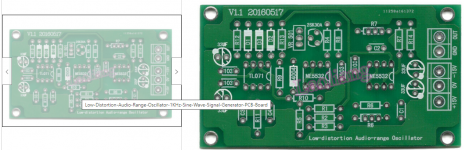
I did a few searches and after that I found the bare PCB pictured one on Ebay.
Is that one a variant of what you use (picture enclosed)?
It uses a 2SK30A. Not sure if that is one of the commonly faked parts or not. I wonder if anyone can recommend a suitable FET that can be reliably/safely sourced. The other parts I have.
If I can get it going I would like to do measurements on some of my kit amplifiers (such as the JLH). In particular I would like to see "as supplied" and then with Mouser/Digikey sources transistors swapped in. Later maybe some capacitor upgrades. I would be up and running already if the built in audio chip was not so bad. Perhaps an external oscillator will let me use the Audigy 2 ZS. Otherwise I need to get yet another sound card. (I already have Audigy 2ZS and an X-Fi. The Audigy 2 ZS worked just fine on older Windows versions.)
For example, I would enjoy looking at the results of the supplied TIP41 compared to Genuine TIP35 (Digikey) to Genuine 2SC5200 (Mouser) to Genuine 2SC6145 (Digikey). Please realize that I understand that the JLH might not sound better (in fact might sound less pleasing) but I would still find it very interesting. Also I would be interested in seeing if I can compare spectra of genuine to "clone" that I have from a variety of kits. Plus I can use the Genuine 2SC5200 & 2SC6145 in a variety of AB kits anyways.
Attachments
- Home
- Amplifiers
- Solid State
- 100W Ultimate Fidelity Amplifier