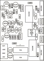
Please share this PCB layoutIt's very nice PCB Artwork.Can u share tharmo transfer PCB layout. Please share your experience during making complete board.
Regards
Gurpreet Singh
hi friends i make first pdcb from apex ax14.
how is first powering. do i need to check some thing? my power is 3vac.
thank you.
how is first powering. do i need to check some thing? my power is 3vac.
thank you.
hi friends i make first pdcb from apex ax14.
how is first powering. do i need to check some thing? my power is 3vac.
thank you.
You should check the bias and you are looking for ~8mV across any of the four 5W 0.33r resistors. Adjust using the P1.
I suggest a Variac, or DBT or you risk fireworks if you have a short. So be careful - all assuming you know how to check and set bias - if not come back and we can get you more detail.
Once you have bias set - check your DC offset on your speaker terminals, before you think about connecting a speaker - needs to be <50mV (should be <20mV per others comments)
Once oyu have verified bias and offset and let it run with nothing connected for at least an hour - only then connect some cheap speakers to check for audio and distortion.
this one i make 2 5watt resistors. i make bias 15mv
i dont put my speakers cause there is 13v dc at output
mje350 (q9) getting hot soo much.
thank you.
Attachments

Last edited:
this one i make 2 5watt resistors. i make bias 15mv
i dont put my speakers cause there is 12v dc at output
thank you.
Once again. Make sure to add a wire from signal ground to PSU star ground.
Once again. Make sure to add a wire from signal ground to PSU star ground.
ty soo much for answers.
i did sgnd to psu gnd. and another thing is q9 mje350 getting soo much hot r19 220R is change the colur but not hot when i see its look like a burning. i check the value and its 220R so i dont change it.
To clarify -
What is your rail voltages?
You have 15mV bias - too high, lower to 8mV
You have 13V DC on the speaker outputs?
Is the MJE350 (q9) the only thing getting hot? Sounds like r19-220r resistor is hot if it’s changing color, and it should not see much current, so something is wrong there.
What is your rail voltages?
You have 15mV bias - too high, lower to 8mV
You have 13V DC on the speaker outputs?
Is the MJE350 (q9) the only thing getting hot? Sounds like r19-220r resistor is hot if it’s changing color, and it should not see much current, so something is wrong there.
To clarify -
What is your rail voltages?
You have 15mV bias - too high, lower to 8mV
You have 13V DC on the speaker outputs?
Is the MJE350 (q9) the only thing getting hot? Sounds like r19-220r resistor is hot if it’s changing color, and it should not see much current, so something is wrong there.
my rail voltage is 30vac
yes bias is 15mv but changing to 15 to 14.9 mv. i will try again with 8mv in 10 min
220R i think some thing happen and i dont see get hot and then change the colour i think but now there is no heat on resistor and resistor value is right 220r. mje350 still getting too much hot in only 2 min work. i check 2 times there is not short on the board. 🙁(
and now after i change bias pot. i have -33v at output. sure i connect sgnd to psu gnd with another cable.
thank you
So what is your +/- rail voltages? So we can relate to your DC offset.
That q9 and it’s compliment 340 should have heatsinks. Do you have heatsinks on them?
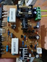
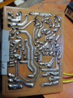
Can you upload some high res pictures from multiple angles? We need to see the board and connections, top and bottom to assist further
That q9 and it’s compliment 340 should have heatsinks. Do you have heatsinks on them?
Can you upload some high res pictures from multiple angles? We need to see the board and connections, top and bottom to assist further
Can I use NX-14 with 44+44DCV PSU? If not, how could I adapt the circuit so it would work this way?
So what is your +/- rail voltages? So we can relate to your DC offset.
That q9 and it’s compliment 340 should have heatsinks. Do you have heatsinks on them?
Can you upload some high res pictures from multiple angles? We need to see the board and connections, top and bottom to assist further
Yes but very small one. i use + - 45vdc
Attachments
Last edited:
Where is you ground? I only see two wires for power.
You do have it mounted to a heatsink, right? Maybe a full system picture. Need some help on your aide to u see stand what might be the problem.
Where did you get your transistors? I got some fakes for the drivers, and caused oscillation and lots of heat. Changed them to authentic ones and it went away immediately.
Where is you ground? I only see two wires for power.
You do have it mounted to a heatsink, right? Maybe a full system picture. Need some help on your aide to u see stand what might be the problem.
Where did you get your transistors? I got some fakes for the drivers, and caused oscillation and lots of heat. Changed them to authentic ones and it went away immediately.
i take out cables for the check board again on computer with schematic 🙁.
i dont have full system yet i take ac from transformer and turn to dc and put capacitors 4x8000uf and then give it to amplifier + - and gnd. sgnd i take with one cable and put on psu gnd. this is hwo i did for wires.
i check all transistors was look good but should i change with another one? i have all transistors just bd139 finish. i buy them from internet in turkey
i find one mistake q1 5401 i make mistake with 5551. i change it stil same.
output have - dc voltage. if i disconnect sgnd from psu gnd then output getting + voltage. but when i connect sgnd to psu gnd then it get - voltage puffff. i hope my mistake dont burn other transistors. 🙁(
output have - dc voltage. if i disconnect sgnd from psu gnd then output getting + voltage. but when i connect sgnd to psu gnd then it get - voltage puffff. i hope my mistake dont burn other transistors. 🙁(
Come on guys...no one to comment on sound quality of the AX14?? ...i am sure many of you have built it..so please come forward and share your experience.
puffff my brain fuses blow. where i making mistake? all transistors working i check all again all resistor values same on schematic. bias 15mv, i try 8mv too nothing change still same. SGND wire to PSU GND. i read many pages but cannot find any thing. some friends have same problem but thats all coming from sgnd wire.
why i am getting -dc voltage.
can any body tell me what should be 5200, 1943, 4793, 1837, bd139 Vbe voltages. and what should be the bias voltage 8 or 15mv for my + - 45vdc
my psu : + - 45Vdc
why i am getting -dc voltage.
can any body tell me what should be 5200, 1943, 4793, 1837, bd139 Vbe voltages. and what should be the bias voltage 8 or 15mv for my + - 45vdc
my psu : + - 45Vdc
puffff my brain fuses blow. where i making mistake? all transistors working i check all again all resistor values same on schematic. bias 15mv, i try 8mv too nothing change still same. SGND wire to PSU GND. i read many pages but cannot find any thing. some friends have same problem but thats all coming from sgnd wire.
why i am getting -dc voltage.
can any body tell me what should be 5200, 1943, 4793, 1837, bd139 Vbe voltages. and what should be the bias voltage 8 or 15mv for my + - 45vdc
my psu : + - 45Vdc
i change 5401 transistors with new ones and now mje350 stop getting heat soomuch. but still getting output 30vdc. and connecting sgnd to psu gnd not change anyting. but there is new problem bias voltage not stoping. i making 15mv and it rising 0,1mv in a second and keep going.
😱😕
i change 5401 transistors with new ones and now mje350 stop getting heat soomuch. but still getting output 30vdc. and connecting sgnd to psu gnd not change anyting. but there is new problem bias voltage not stoping. i making 15mv and it rising 0,1mv in a second and keep going.
😱😕
Something's blown. Still4given had posted a pdf / asc file with voltages few pages back . find it and check accordingly
puffff my brain fuses blow. where i making mistake? all transistors working i check all again all resistor values same on schematic. bias 15mv, i try 8mv too nothing change still same. SGND wire to PSU GND. i read many pages but cannot find any thing. some friends have same problem but thats all coming from sgnd wire.
why i am getting -dc voltage.
can any body tell me what should be 5200, 1943, 4793, 1837, bd139 Vbe voltages. and what should be the bias voltage 8 or 15mv for my + - 45vdc
my psu : + - 45Vdc
Something's blown. Still4given had posted a pdf / asc file with voltages few pages back . find it and check accordingly
ty so much. i am looking for his write,
Something's blown.
hi.
i check voltages from 5200 to c4793, mje350, bc547
and from 1943 to a1837, mje340, bc557
bc547 Vbe: 32V
bc557 Vbe: 557mV !!!!??????
i think bc557 gone i am not sure but i cannot test it cause i dont have that transistor right now.
can i use 2n551 and 5401 For bc547 and bc557 ?
- Home
- Amplifiers
- Solid State
- 100W Ultimate Fidelity Amplifier