I found the AX14 very well behaved, not a sign of switch on/off thump.
With out connecting the input signal ?
With out connecting the input signal ?
With input connected. A floating input is likely to have variable results I think.
With input connected. A floating input is likely to have variable results I think.
With input connected, am not getting any issues
Only problem is it’s not center voiced, left channel gain is more than right channel
Check you speaker polarity. Having one channel out of phase will give that impression.
If that checks ok, input signal of 1Vac with a 1k sine wave and measure the Vac on the speaker outputs. That will show you if you have true issue.
If that checks ok, input signal of 1Vac with a 1k sine wave and measure the Vac on the speaker outputs. That will show you if you have true issue.
AX14 gain
Can anybody tell me the gain of the AX14? Will be useful to know when I integrate it into my exiting active 3-way
Can anybody tell me the gain of the AX14? Will be useful to know when I integrate it into my exiting active 3-way
voltage gain is approx 39, ratio of R11 and R8.
You can reduce gain by increasing R8, say 1k.
You can reduce gain by increasing R8, say 1k.
Check you speaker polarity. Having one channel out of phase will give that impression.
If that checks ok, input signal of 1Vac with a 1k sine wave and measure the Vac on the speaker outputs. That will show you if you have true issue.
I have checked the polarity and it is correct
With input connected, am not getting any issues
Only problem is it’s not center voiced, left channel gain is more than right channel
as suggested previously here by member, check RMS voltage at output when both channels are supplied with 0.5-1VRMS input at 1kHz.
if they are different, then start checking all resistor values , especially NFB resistors, emitter resistors, and others.
hiss when no input is connected , means amp is picking up some RF OR it could also be oscillating.
for oscillation, check zobel resistor for heating up.
there is definitely something wrong with components/wiring/surroundings/ grounding on PSU.
Have you by any chance connected the input ground to chassis earth?
also do you have volume control?, I do not believe in any volume control except for high quality stepped volume control.
if its ordinary 16mm pot, has its body been grounded?
also is every wire is twisted properly and no high current / AC wires near input section and signal wiring?
Last edited:
as suggested previously here by member, check RMS voltage at output when both channels are supplied with 0.5-1VRMS input at 1kHz.
if they are different, then start checking all resistor values , especially NFB resistors, emitter resistors, and others.
hiss when no input is connected , means amp is picking up some RF OR it could also be oscillating.
for oscillation, check zobel resistor for heating up.
there is definitely something wrong with components/wiring/surroundings/ grounding on PSU.
Have you by any chance connected the input ground to chassis earth?
also do you have volume control?, I do not believe in any volume control except for high quality stepped volume control.
if its ordinary 16mm pot, has its body been grounded?
also is every wire is twisted properly and no high current / AC wires near input section and signal wiring?
Hi prasi,
Yes i have connected the input ground to chassis - should i connect or not?
There is no volume pot connected
Mains ground is connected to chassis and from chassis wire is connected one end of ground loop breaker and the other end is connected to psu ground
From psu ground one wire is connected to amp ground and one wire goes to speaker ground and signal ground
Please let me know if any thing wrong with wirings

ok, its picking up all the noise from dumpyard of your home and neighbor's earth. It is the dirtiest grounding point. input GND should be connected to PSU ground at the farthest point from high currents.
read hifisonix grounding guidance.
regards
prasi
read hifisonix grounding guidance.
regards
prasi
Last edited:
Use PSU100
YouTube
hi again mr mile...i have no space in my amplifier box ..i find below site a short protection circuit....for protect my output transistor or mosfet or stk ic...please see this site and tell your idea...in fact i need a circuit that when my out put + and - conected together , my amplifier circuit be safe.
Amplifier Short/Overload Protection Circuit - 2 Ideas Discussed | Homemade Circuit Projects
Last edited:
voltage gain is approx 39, ratio of R11 and R8.
You can reduce gain by increasing R8, say 1k.
Thanks Prasi. So thats around 32db if I got that right. Seems high but I guess with a higher output amp the gain needs to be higher to achieve rated output.
Anyway easily adjusted by my DSP crossover.
Last edited:
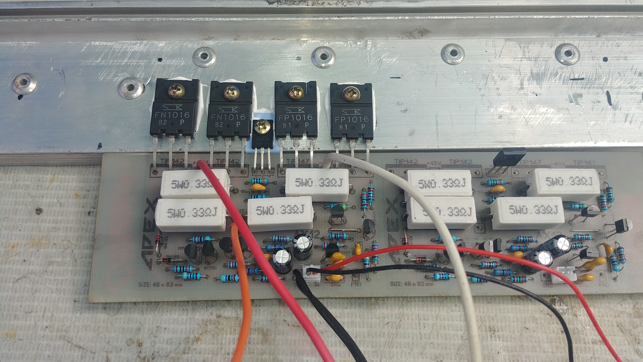
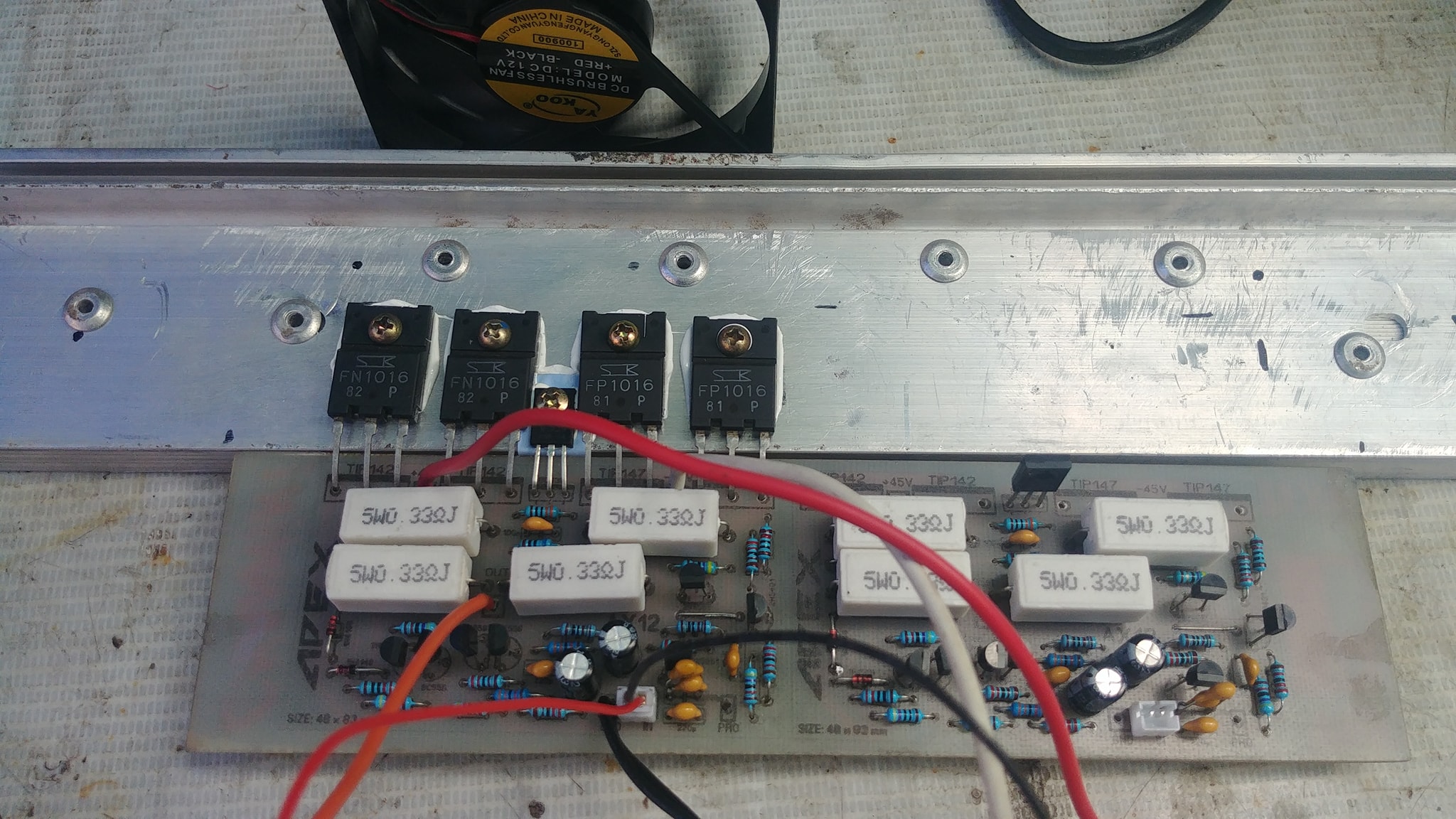
hi i made another ax14 its working well but i have 50mv offset at output also bias voltages are different on emitter resistors at c5200's side its about 8.7mv and at 1943's side its about 14.4 mv what is the problem?
hi i made another ax14 its working well but i have 50mv offset at output also bias voltages are different on emitter resistors at c5200's side its about 8.7mv and at 1943's side its about 14.4 mv what is the problem?
Congrats Rehman on finishing the AX14
Is the sound balanced on both channels?
Congrats Rehman on finishing the AX14
Is the sound balanced on both channels?
yes sound is balanced and sound quality is good too. i have also connected a bjt pre amp with ax 14.
Apex Fan control PCB with photosensitive dry film
hi gurpreet from where you pkoto sensetive dry film.
thanks
My AX12 works great.
Some preamp to work together I put the p30zf but it did not work.
sorry my bad english just google translator
😛ag
Some preamp to work together I put the p30zf but it did not work.
sorry my bad english just google translator
😛ag
Attachments

- Home
- Amplifiers
- Solid State
- 100W Ultimate Fidelity Amplifier