Hello Chatchai,
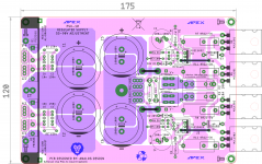
Please find attached herewith the stuffing guide and sch. It only contains ground lift components (10R+ anti parallel diodes as an option) as additional. These can be also left out and i/p ground can be connected to PSU ground as per original APEX advice.
Also it is with 2 pairs of o/p devices.
Otherwise the schematic follows the original AX-14. I am collecting the parts to build it.
regards
Prasi
I missed this post a few days ago..
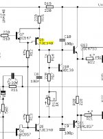
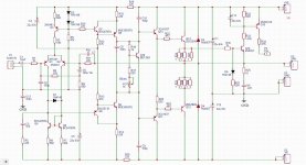
I've been getting the finals parts ready for this build and noticed that Q9 on Prasi's schematic should be MJE350 (PNP) not MJE340 as marked.
I'm going to use MJE15034/35 as alternates to the seemingly unobtainium 2SC4793 and 2SA1837 complementary.
Attachments
Last edited:
Hi Avtech,
Yes, you are correct. I dont know how that mistake crept in...
It was later corrected here.
100W Ultimate Fidelity Amplifier
All the best for your build.
regards
Prasi
Yes, you are correct. I dont know how that mistake crept in...
It was later corrected here.
100W Ultimate Fidelity Amplifier
All the best for your build.
regards
Prasi
Thank you!
Fantastic, thank you. Are gerber files available please? 🙂
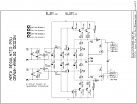
Here is a version of the APEX regulated PSU if any one is interested.
PSU10
regards
Prasi
Fantastic, thank you. Are gerber files available please? 🙂
Fantastic, thank you. Are gerber files available please? 🙂
here you go. As per APEX posts I think about 10V differential between input and output voltage would be better.
It can be manufactured double sided or etched single sided and use jumpers as marked.
regards
Prasi
Attachments
Last edited:
what ac in and dc out is this PSU10 suitable for? what about current?
Thanks
Studio Reference Amplifier
hi all between ax20 and ax14 which one is superior in sound quality when using multiple output transistors?
hi all between ax20 and ax14 which one is superior in sound quality when using multiple output transistors?
i build ax11 two months ago it sounded good. latter on i build ax20 and fell in love with i personally will prefer ax20 both have high quality output but with ax20 you will have more power margin.
Hi all,
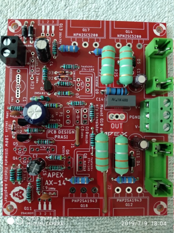
I built the AX14, able to set bias, but there is 11v dc on the output. I don't remember exactly how many times i checked components and layout, please help me.
Thanks in advance.
Regards.
Anoop
I built the AX14, able to set bias, but there is 11v dc on the output. I don't remember exactly how many times i checked components and layout, please help me.
Thanks in advance.
Regards.
Anoop
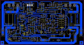
AX14 images
Here is my make.
Hi all,
I built the AX14, able to set bias, but there is 11v dc on the output. I don't remember exactly how many times i checked components and layout, please help me.
Thanks in advance.
Regards.
Anoop
Here is my make.
Attachments
Hi all,
I built the AX14, able to set bias, but there is 11v dc on the output. I don't remember exactly how many times i checked components and layout, please help me.
Thanks in advance.
Regards.
Anoop
check your power supply if it is symmetrical and look with your dmm if there are any dry joints.
Here is my make.
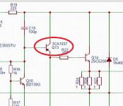
Q13 is wrong. It must be npn instead of pnp...
Sajti
Q13 is wrong. It must be npn instead of pnp...
Sajti
Thanks for the reply, actually a proper footprint was not available for that transistor so i put that there deliberately, in actual PCB i have fitted the proper one.
Thanks for your concern.
Warm regards.
Anoop.
Q13 is wrong. It must be npn instead of pnp...
Sajti
I would second that.
Attachments
Hi all,
I built the AX14, able to set bias, but there is 11v dc on the output. I don't remember exactly how many times i checked components and layout, please help me.
Thanks in advance.
Regards.
Anoop
First thing to check is that you have a separate ground wire from the input ground to the star ground.
First thing to check is that you have a separate ground wire from the input ground to the star ground.
Mr. Mile had said he will put that sentence in his signature once😀😀
Thanks for the reply, actually a proper footprint was not available for that transistor so i put that there deliberately, in actual PCB i have fitted the proper one.
Thanks for your concern.
Warm regards.
Anoop.
mistake with orientation of input coupling cap... even bigger one with NFB cap orientation.
Also while asking for debugging, best to upload some close up pics ..
Hi guys,
I'm about to finish apex ax 14, a question, for the BC557 and BC 547, can I use both those with the abbreviation "B"?
thanks a lot
I'm about to finish apex ax 14, a question, for the BC557 and BC 547, can I use both those with the abbreviation "B"?
thanks a lot
Hello mprivitera1,
Yes, you may use BC547B/BC557B.
Also there was no requirement of Jumpers as you have the manufactured double sided PCBs. The jumpers were provided for single sided home etching, though it doesnt hurt.
regards
Prasi
P.S. the power resistors are meant to be something like this, though whatever suits one/ available in parts bin is ok to use... 5pcs 5W 0.1 0.15 0.22 0.25 0.33 0.5 ohm Non inductive Cement Resistor 5% 0.1R 0.15R 0.22R 0.25R 0.33R 0.5R-in Resistors from Electronic Components & Supplies on Aliexpress.com | Alibaba Group
P.S. 2: Mount Q10 on one of the output transistors
P.S. 3: Q1 Q2 can be thermally coupled for better offset behavior.
Last edited:
- Home
- Amplifiers
- Solid State
- 100W Ultimate Fidelity Amplifier