Is there a BOM for the Prasi board shown just above in #11459? I went through a good chunk of the posts here and didn't find one.
APEX AX-14 all files 😀
Hi invader,
I think I posted it somewhere, but here it is again for convenience.
Here is the order link.
apex ax14_total new_2pairs_rev1 - Share Project - PCBWay
regards
Prasi
Hi invader,
I think I posted it somewhere, but here it is again for convenience.
Here is the order link.
apex ax14_total new_2pairs_rev1 - Share Project - PCBWay
regards
Prasi
Attachments
-
BOM-apex ax14_total new_2pairs_rev1_sch clean up.zip15.7 KB · Views: 649
-
apex ax14_total new_2pairs_rev1_sch clean up_cu bottom.pdf59.3 KB · Views: 666
-
apex ax14_total new_2pairs_rev1_sch clean up_silk top.pdf67.2 KB · Views: 627
-
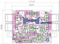 2 pairs ax-14.png151.7 KB · Views: 2,068
 -
 2-pairs sch.png21.9 KB · Views: 2,044
Last edited:

Hello mprivitera1,
Yes, you may use BC547B/BC557B.
Also there was no requirement of Jumpers as you have the manufactured double sided PCBs. The jumpers were provided for single sided home etching, though it doesnt hurt.
regards
Prasi
P.S. the power resistors are meant to be something like this, though whatever suits one/ available in parts bin is ok to use... 5pcs 5W 0.1 0.15 0.22 0.25 0.33 0.5 ohm Non inductive Cement Resistor 5% 0.1R 0.15R 0.22R 0.25R 0.33R 0.5R-in Resistors from Electronic Components & Supplies on Aliexpress.com | Alibaba Group
P.S. 2: Mount Q10 on one of the output transistors
P.S. 3: Q1 Q2 can be thermally coupled for better offset behavior.
thanks Prasi,
you think to use these resistances KNP05SJ033KA10 ROYAL OHM - Resistore: a filo KNP05WS-0R33 | TME - Componenti elettronici
I have problems ?
In relation to the Q10 do you mean to mount it on the heatsink of the power transistors?
Thanks
thanks Prasi,
you think to use these resistances KNP05SJ033KA10 ROYAL OHM - Resistore: a filo KNP05WS-0R33 | TME - Componenti elettronici
I have problems ?
In relation to the Q10 do you mean to mount it on the heatsink of the power transistors?
Thanks
No, no mprivitera1,
I was merely meaning to convey the PCB foot print is suitable for the BPR56 type of resistors. The one you used, are perfect , no problems there.
For Q10, yes, mounting it on any output transistor with a single bolt would be better. It should have thermal paste on between output transistor top and Q10 back side. So it senses the temperature rise / fall quickly.
One can also mount it on main heatsink, but I feel above option is better as it would not require drilling and tapping of hole for Q10.
regards
Prasi
Last edited:
No, no mprivitera1,
I was merely meaning to convey the PCB foot print is suitable for the BPR56 type of resistors. The one you used, are perfect , no problems there.
regards
Prasi
thanks for the reply
AX14 offset
Thanks Mr Prasi for pointing out the errors. I have corrected the errors, still the offset voltage is there, i have a feeling that the 2SA1943 is slightly warmer than its counterpart, any way the current drawn is equal in both sides, appx 105 mA.
Thanks and regards.
mistake with orientation of input coupling cap... even bigger one with NFB cap orientation.
Also while asking for debugging, best to upload some close up pics ..
Thanks Mr Prasi for pointing out the errors. I have corrected the errors, still the offset voltage is there, i have a feeling that the 2SA1943 is slightly warmer than its counterpart, any way the current drawn is equal in both sides, appx 105 mA.
Thanks and regards.
Air Coil
A basic question: Why some amps, like Apex AX14 has no air coil before speaker output?
See example with coils here please:

A basic question: Why some amps, like Apex AX14 has no air coil before speaker output?
See example with coils here please:
Here is a version of the APEX regulated PSU if any one is interested.
PSU10
regards
Prasi
One thing I forgot to mention for this PSU.. Since it uses PCB3508 SIP-4 type of rectifiers, they can be replaced with one of my LT4320 SMD PCBs.
LT4320 based active rectifier
regards
Prasi
A basic question: Why some amps, like Apex AX14 has no air coil before speaker output?
See example with coils here please:
The coil with a parallel resistor can be mounted on the speaker terminal. Either hanging in air or using a small pcb like this.
universal thiele circuit
A basic question: Why some amps, like Apex AX14 has no air coil before speaker output?
The coil with a parallel resistor can be mounted on the speaker terminal. Either hanging in air or using a small pcb like this.
universal thiele circuit
Ah so 🙂 Good to know. Thanks!
Hi invader,
I think I posted it somewhere, but here it is again for convenience.....
thanks!
I actually found the design on PCBway first and then realized I'd been reading about it here.
That's the one. I had just discovered that there were projects saved on there that could be searched through when I was looking at one and noticed the "AX-14" on it 🙂
thanks for the reply
One more thing, FOr C9 C10 use min 100V parts or better yet 200V parts.
C318C101J2G5TA KEMET | Mouser India
Ordinary 50V x7r ceramic cap is not suitable. Please have a look at my BoM posted above recently.
Those are the ones I have in my cart now.
Thank you for going to all the work to put together the full BOM as well as the PCB. It really makes this so much more accessible to the hobbyist like myself. Not having to guess at which parts will fit and work properly makes it much easier.
Thank you for going to all the work to put together the full BOM as well as the PCB. It really makes this so much more accessible to the hobbyist like myself. Not having to guess at which parts will fit and work properly makes it much easier.
thanks for the share. please share pcb files in pdf also
also just wondering
 is apex ax14 with multiple pairs better than apex 500watts pa , in terms of stability and durability?
AX14 offset voltage
Hi all,
As suggested by Mr Terry and Prasi, connected PS ground to the input ground, the problem vanished away. An offset voltage of 11v to 65mv. Is 65mv acceptable ?
Thanks to all who spent their valuable time for me.
Here is my make.
Hi all,
As suggested by Mr Terry and Prasi, connected PS ground to the input ground, the problem vanished away. An offset voltage of 11v to 65mv. Is 65mv acceptable ?
Thanks to all who spent their valuable time for me.
Hi all,
As suggested by Mr Terry and Prasi, connected PS ground to the input ground, the problem vanished away. An offset voltage of 11v to 65mv. Is 65mv acceptable ?
Thanks to all who spent their valuable time for me.
Great to hear that sorted it out for you. Perhaps one day Mile will add that info to the first post so that folks don't continue to have this problem.
65mV won't hurt anything but you can probably get that a little lower by matching Q1 and Q2 a little more closely. Enjoy your amp.
Blessings, Terry
Is it possible to replace the .33 ohm resistor with .22 ohm, if so what changes are to be carried out, in AX14 Amplifier.
Regards.
Regards.
- Home
- Amplifiers
- Solid State
- 100W Ultimate Fidelity Amplifier