.....The Offset has come down by a wee bit,It now stands at -2.5mv (earlier -2.8 to -3mv) on one channel and -1.8mv (earlier 2.2 to 2.4mv) on the other.........................The Bias keeps decreasing.
I had kept the bias approx 81ma (27mv) and it keeps dropping to 25-26mv
Regards.
Don't break your head over the offset . Offset will drift with time . Any offset below +/- 10 mV is great ! In actual use any offset below +/- 50 mV is fine ! Your offset is perfectly OK.
Same way , the bias will drift ! If it drops with time it's probably just settling down to a nominal value. Bias is in any case set only after 20 minutes or so ! Even then , after you set it , since the current levels have changed it will settle to a different value ! So stop bothering about it. As long as it does not start increasing progressively with time it will not get into thermal runaway and disaster !
Dropping from 27mV to 25 mV is nothing to be worried about ! If everything is working as it should , just leave it as it is ! You don't need an exact 80mA bias setting. +/- 20% should not be audible at all ( sometimes even more !).
Hi Apex
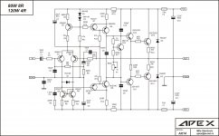
What is the difference between SR series (sr150 sr200 etc.) and AX series?
AX is simple amp with high performance, made for start in DIY hi-fi amps.
Last edited:
View attachment 540309
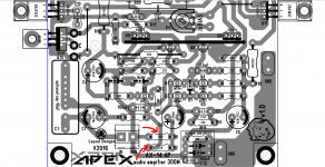
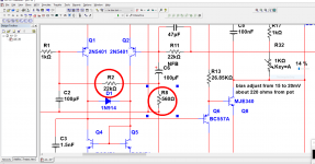
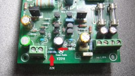
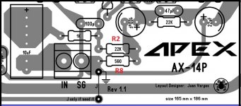
R2 and R8 are reversed that is my fault sir I guess I was fallowing the older AX-14 schematic later on they fixed on other post number and that was a long time ago, change R2 to 22k and R8 to 560 ohms you will notice you will get more power sorry for my mistake sir
Best Regards
Juan
Hi,
Just wanted to update on the thermal coupling, As per suggestions I changed the coupling devices and have had it now for 4 days.
The Offset has come down by a wee bit,It now stands at -2.5mv (earlier -2.8 to -3mv) on one channel and -1.8mv (earlier 2.2 to 2.4mv) on the other.
Also one thing I have noticed over the period of a month or so since the Amp was built and was to put to play,The Bias keeps decreasing.
I had kept the bias approx 81ma (27mv) and it keeps dropping to 25-26mv,I have set it multiple times but it still continues to drop,Is it normal ??
Regards.
R2 and R8 are reversed that is my fault sir I guess I was fallowing the older AX-14 schematic later on they fixed on other post number and that was a long time ago, change R2 to 22k and R8 to 560 ohms you will notice you will get more power sorry for my mistake sir
Best Regards
Juan
Attachments
Last edited:
Hi,
Thanks a lot for reply !
Yes I know but I just wanted it to be as close to Zero as possible (call me nuts,but its just.....)
Ok noted,Again I was just trying to keept it stable and was wondering as to why it's happening.
Yes Sir,I have set the bias only after the first half hour of the Amp being switched on. I switch on and take a reading and leave on for a min of 12+hrs taking reading constantly every 2hrs or so (I switch on at morning 10Am and keep it on till 12-1Am in the night).
I usually listen to music in the night after 11 or 12 as the its the best time for it (ambient noise,power noise etc being at their lowest).
Anyways Thanks once again for replying,I will keep things in mind.
I doubt that juan, I checked and double checked it's correct on the PCB,as its in the circuit you posted above. I have even checked Willys and other as well,R2 22K goes neagtive pin of C6 after R1 1K and R8 560R goes to negative pin of C6 from signal ground.
Regards.
Thanks a lot for reply !
Don't break your head over the offset . Offset will drift with time . Any offset below +/- 10 mV is great ! In actual use any offset below +/- 50 mV is fine ! Your offset is perfectly OK.
Yes I know but I just wanted it to be as close to Zero as possible (call me nuts,but its just.....)
Same way , the bias will drift ! If it drops with time it's probably just settling down to a nominal value. Bias is in any case set only after 20 minutes or so ! Even then , after you set it , since the current levels have changed it will settle to a different value ! So stop bothering about it. As long as it does not start increasing progressively with time it will not get into thermal runaway and disaster !
Dropping from 27mV to 25 mV is nothing to be worried about ! If everything is working as it should , just leave it as it is ! You don't need an exact 80mA bias setting. +/- 20% should not be audible at all ( sometimes even more !).
Ok noted,Again I was just trying to keept it stable and was wondering as to why it's happening.
Yes Sir,I have set the bias only after the first half hour of the Amp being switched on. I switch on and take a reading and leave on for a min of 12+hrs taking reading constantly every 2hrs or so (I switch on at morning 10Am and keep it on till 12-1Am in the night).
I usually listen to music in the night after 11 or 12 as the its the best time for it (ambient noise,power noise etc being at their lowest).
Anyways Thanks once again for replying,I will keep things in mind.
R2 and R8 are reversed that is my fault sir I guess I was fallowing the older AX-14 schematic later on they fixed on other post number and that was a long time ago, change R2 to 22k and R8 to 560 ohms you will notice you will get more power sorry for my mistake sir
I doubt that juan, I checked and double checked it's correct on the PCB,as its in the circuit you posted above. I have even checked Willys and other as well,R2 22K goes neagtive pin of C6 after R1 1K and R8 560R goes to negative pin of C6 from signal ground.
Regards.
Attachments
Hi,
Thanks a lot for reply !
Yes I know but I just wanted it to be as close to Zero as possible (call me nuts,but its just.....)
Ok noted,Again I was just trying to keept it stable and was wondering as to why it's happening.
Yes Sir,I have set the bias only after the first half hour of the Amp being switched on. I switch on and take a reading and leave on for a min of 12+hrs taking reading constantly every 2hrs or so (I switch on at morning 10Am and keep it on till 12-1Am in the night).
I usually listen to music in the night after 11 or 12 as the its the best time for it (ambient noise,power noise etc being at their lowest).
Anyways Thanks once again for replying,I will keep things in mind.
I doubt that juan, I checked and double checked it's correct on the PCB,as its in the circuit you posted above. I have even checked Willys and other as well,R2 22K goes neagtive pin of C6 after R1 1K and R8 560R goes to negative pin of C6 from signal ground.
Regards.
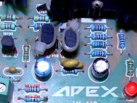
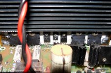
question sir does Q10 BD139 well attached to main heat sink ? I mean nicely secure with insulation and thermal compound
Hi,
Yes Absolutely,Its secured and have put in Kapton tape with the Mica,Heatsink compound applied.
May I know why you ask ??
Regards.
question sir does Q10 BD139 well attached to main heat sink ? I mean nicely secure with insulation and thermal compound
Yes Absolutely,Its secured and have put in Kapton tape with the Mica,Heatsink compound applied.
May I know why you ask ??
Regards.
Attachments
Hi,
Yes Absolutely,Its secured and have put in Kapton tape with the Mica,Heatsink compound applied.
May I know why you ask ??
Regards.
yes because BD139 track temperature and according to heat sink temperature it will have and internal resistance that will fluctuate giving different bias results 🙂
Hi,
Absolutely no need,You had perhaps missed that you corrected it.No biggie ! Even otherwise its out duty while assembling to check both Schematic and PCB.
That's the very reason I asked the question,I will in some time change the heatsink to a bigger one and then see how it goes.
This is a temp setup just to check the sound and make sure things are in working order before I shift the whole thing to a proper cabinet (need to get one done).
Regards.
errata yes sir you were right I did changed and it was correct before I made a mistake I apologize
Absolutely no need,You had perhaps missed that you corrected it.No biggie ! Even otherwise its out duty while assembling to check both Schematic and PCB.
yes because BD139 track temperature and according to heat sink temperature it will have and internal resistance that will fluctuate giving different bias results
That's the very reason I asked the question,I will in some time change the heatsink to a bigger one and then see how it goes.
This is a temp setup just to check the sound and make sure things are in working order before I shift the whole thing to a proper cabinet (need to get one done).
Regards.
 ufff man I have a short circuit in my brain
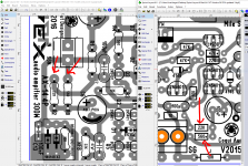
Change(s) for 12V Output.
I'm wanting to try Mr. Mile's simple shunt supply for my op-amp based preamp. Terry was nice enough to share his layout with me.
Are the 2 zener diodes all that need to be changed so it will output 12V instead of 18V?
I'll be using BC550/560 and A992/C1845 for the TO-92 transistors and BD241/242 for the larger transistors.
I am not familiar with shunt supplies having used only LM317/337 supplies, so I have a couple more questions:
1) Will the BD devices get really hot powering 3 op-amps like the NE5534?
2) Is it true you have to have a load on a shunt supply or it will get very hot?
3) What wattage zeners will I need?
Thanks...
Attachments
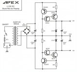
1W 12V zener diodes is all that need to be changed so it will output 12V instead of 18V.I'm wanting to try Mr. Mile's simple shunt supply for my op-amp based preamp. Terry was nice enough to share his layout with me.
Are the 2 zener diodes all that need to be changed so it will output 12V instead of 18V?
I'll be using BC550/560 and A992/C1845 for the TO-92 transistors and BD241/242 for the larger transistors.
I am not familiar with shunt supplies having used only LM317/337 supplies, so I have a couple more questions:
1) Will the BD devices get really hot powering 3 op-amps like the NE5534?
2) Is it true you have to have a load on a shunt supply or it will get very hot?
3) What wattage zeners will I need?
Thanks...
Load with 3 op-amps or without load BD will have same themperature.
Regards
Thanks for your reply Mr. Mile.
Your AX11TEF sounds like it has some killer bass in your video!
Your AX11TEF sounds like it has some killer bass in your video!
Thanks for your reply Mr. Mile.
Your AX11TEF sounds like it has some killer bass in your video!
AX11TEF can work with 2R load and it's good for subwoofer amp.
Nice, is it work?
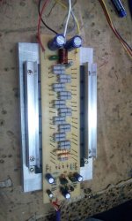
If the o/p's are so closely spaced together, will it not create problems? some (center ones), will get too hot?
reg
Prasi
If the o/p's are so closely spaced together, will it not create problems? some (center ones), will get too hot?
reg
Prasi
Fan is must for this amp. I use fan with on/off switch for 3 pair AX20.
Regards
Sonal Kunal.
- Home
- Amplifiers
- Solid State
- 100W Ultimate Fidelity Amplifier