There is FX8
Hi Mile,
any changes in FX8 to 2sk1058 / 2sj162 ?
best regards
Hi Mile,
any changes in FX8 to 2sk1058 / 2sj162 ?
best regards
No changes
Regards
Hi Mile,
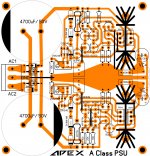
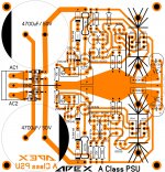
I did a new layout based on the one that Alex did but I changed the Jfets to 2SK246 so I changed the pinout to match those. I also fixed the pinout on the TO-220 transistors. I built it but it doesn't work so I figure that I have something wrong in the layout. The output is just full voltage and won't adjust. I have been over and over the layout and I just can't find the issue. I'm hoping you or one of the other guys who is good at layout will be able to help me find it.
Thanks, Terry
Attachments
ax11 amp apex
shalum apex thank you for your reply, i'm new to this forum and big thanks for that schematic fx8 mosfet power stage of this amp, what about microphone preamp circuit and mixer circuit can you post some schematic? if possible?
shalum apex thank you for your reply, i'm new to this forum and big thanks for that schematic fx8 mosfet power stage of this amp, what about microphone preamp circuit and mixer circuit can you post some schematic? if possible?
ELECTRIC GUITAR PREAMP
SHALUM, HELLO TO YOU APEX AUDIO HAVE A NICE DAY TO YOU CAN YOU PLEASE SHARE SOME ELECTRIC GUITAR PREAMP? APPRECIATE
REGARDS............
SHALUM, HELLO TO YOU APEX AUDIO HAVE A NICE DAY TO YOU CAN YOU PLEASE SHARE SOME ELECTRIC GUITAR PREAMP? APPRECIATE
REGARDS............
Hi Mile,
I did a new layout based on the one that Alex did but I changed the Jfets to 2SK246 so I changed the pinout to match those. I also fixed the pinout on the TO-220 transistors. I built it but it doesn't work so I figure that I have something wrong in the layout. The output is just full voltage and won't adjust. I have been over and over the layout and I just can't find the issue. I'm hoping you or one of the other guys who is good at layout will be able to help me find it.
Thanks, Terry
Set 5k pots to 0R and measure voltages on 15k resistors...
shalum apex thank you for your reply, i'm new to this forum and big thanks for that schematic fx8 mosfet power stage of this amp, what about microphone preamp circuit and mixer circuit can you post some schematic? if possible?
Go to thread http://www.diyaudio.com/forums/analog-line-level/167363-mic-line-eq-preamps.html
Hi Mile,
I did a new layout based on the one that Alex did but I changed the Jfets to 2SK246 so I changed the pinout to match those. I also fixed the pinout on the TO-220 transistors. I built it but it doesn't work so I figure that I have something wrong in the layout. The output is just full voltage and won't adjust. I have been over and over the layout and I just can't find the issue. I'm hoping you or one of the other guys who is good at layout will be able to help me find it.
Thanks, Terry
Terry, double check the connecting tracks of minus rail starting at the output BD241/242 emitter to emitter connection. Compared with the schematic I think the track should be connected on the other leg of 1uf...not on the 15k node.
Last edited:
Terry, double check the connecting tracks of minus rail starting at the output BD241/242 emitter to emitter connection. Compared with the schematic I think the track should be connected on the other leg of 1uf...not on the 15k node.
Good catch! I had hoped a fresh set of eyes would see something I was missing. Hopefully that will fix it. I'll report back.
Blessings, Terry
Terry nice layout you have there, congratulation - I hope you will find the problem..
Greetings
Greetings

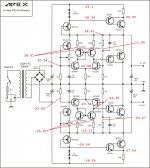
Set 5k pots to 0R and measure voltages on 15k resistors...
Schematic with voltages attached. I fixed the layout in regard to negative output rail
Attachments
CFA Mosfet Amplifier
Weird looking schematic, but it can be good anyway.
Sajti
Schematic with voltages attached. I fixed the layout in regard to negative output rail
5k pot is shorted?
5k pot is shorted?
Yes. I currently have a jumper soldered across them to be sure.
I'm not good in electronics, but I see two problems:
1. On plus rail, wiper of trimpot is connected to 15k resistor. On minus rail is not. Maybe Mile missed connection line.
2. This is shunt regulator. You can't leave output opened. Output must be loaded.
1. On plus rail, wiper of trimpot is connected to 15k resistor. On minus rail is not. Maybe Mile missed connection line.
2. This is shunt regulator. You can't leave output opened. Output must be loaded.
Yes. I currently have a jumper soldered across them to be sure.
Positive rail measurement must be wrong, but negative is ok. Set 5k in negative rail to maximum resistance and measure voltages.
Positive rail measurement must be wrong, but negative is ok. Set 5k in negative rail to maximum resistance and measure voltages.
I remeasured everything. Red numbers with trimmers at 0R and Blue numbers are with trimmers set to 5k.
Attachments

I remeasured everything. Red numbers with trimmers at 0R and Blue numbers are with trimmers set to 5k.
Can you test your fets...
FIELD EFFECT TRANSISTOR; THE J-FET | ECE Undergraduate Laboratory
- Home
- Amplifiers
- Solid State
- 100W Ultimate Fidelity Amplifier