Hi, I have checked the layout again. I could not find the error!
regards Olaf
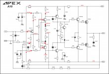
A10 and V10 work well in multisim 14 ... can you measure voltages on 2Sk117 pins and VAS resistors?
Last edited:
Very helpful. Thank you.
Any chance you could add on the currents, maybe in a different colour?
Are you really running this without any input filtering?
Any chance you could add on the currents, maybe in a different colour?
Are you really running this without any input filtering?
Hi, yes, I can try to measure the currents. But that's not simple in the small circuit board.
Andrew, I am novice in audio amplifiers. I just like to make printed circuit boards 🙂. So I don't understand you question. The input is shorted and directly connected to PGND. Which filter should I use?
regards Olaf
Andrew, I am novice in audio amplifiers. I just like to make printed circuit boards 🙂. So I don't understand you question. The input is shorted and directly connected to PGND. Which filter should I use?
regards Olaf
I think AndrewT means that the amplifier as it passes continuously from the inlet to the outlet.
It's correct AndrewT?
It's correct AndrewT?
I can try to measure the currents. But that's not simple in the small circuit board.
you don't need to measure. I = V/R
if you have already measured the volts drop across a resistor then you know the current. It helps complete the diagram if you add on that extra information.
DO NOT try to insert an ammeter to measure actual operational currents.
Last edited:
the input shows a 330k defining Rin......................... So I don't understand you question. The input is shorted and directly connected to PGND. Which filter should I use?..............
and shows a 100pF with no preceding impedance.
Neither of these are filters.
DC to light wave will pass into the first stage.
That 2sk117 is going to have a demanding duty coping with all that interference.
And if the input pulse is faster than the opamp can respond, then the Vgs of the jFET could easily be exceeded and become damaged, if not actually blow up.
If one wants to run DC coupled amplifiers, one should look at what other ancillaries are required to maintain reliable operation.
Any and every piece of audio gear should have RF attenuation filtering on the input.
Hi Andrew, ok.
Can you show me a simple test solution, what to do to save the jFET. Then I will replace the 2SK117 and try again. OK?
regards Olaf
Can you show me a simple test solution, what to do to save the jFET. Then I will replace the 2SK117 and try again. OK?
regards Olaf
add a real resistor between the input and the 100pF
use 1k0 as an example.
The highest F-3dB will be defined by the two values 1k0 & 100pF
The cable will have some impedance. This will increase the filtering. The problem with using the cable alone is that a short cable will have very low impedance and a very long cable will capture more interference. The RF attenuation has to occur as the cable enters the chassis screen.
I add a 47pF at the input socket as well as the RC at the PCB input.
Read about what can go wrong with DC coupled amplifiers. Your speakers will take fright and refuse to allow you to connect them to the unprotected amplifier. They will lift up their skirts and dash for the open door!
Hi Andrew, thanks for the explanation. I will insert the resistor and then try again 🙂.
regards Olaf
regards Olaf
personally, I use 240kHz as my RF filter.
That requires a 680ns RC time constant.
I can get that 680ns (0.68us) from any R&C combination that multiplied give that result.
i.e. 1k0 & 680pF, or 680r * 1nF, or 300r & 2n2F
There is a lot of variation in RF filtering. Some look for only 300ns of filtering other look for 1500ns of filtering. You are likely to be happy with something inside that range. Try different values until you find the highest RC that does not remove any extreme treble information.
Your existing 100pF is extremely small, you may want to look at increasing it to at least 220pF and maybe as high as 2200pF. Try that as well.
Once your capacitor value is installed and fixed it is MUCH EASIER to adjust the resistor value by adding a parallel value tack soldered across the existing.
If the track is accessible, you can even add an SMD resistor across a narrow cut in the track.
I have done this more than a dozen times when there is no room to added a through hole resistor. either the track is too narrow to drill through or too short.Hi, I have understood. The idea with the SMD resistor is super. I will report.
Regards Olaf
And the extra resistor is on the other side, so can usually be added, or removed, due to easy accessibility on a crowded PCB.
I have even added the extra resistor to form the Dr Cherry feedback. Actually two smd resistors to give the 2times value needed to match the existing upper leg feedback resistor.
Last edited:
Hi, I have inserted a SMD resistor 1K0 and changed the capacitor from 100p to 680p. 2SK117 and opamp are also new.
Unfortunately, no change. The output of the TL071 is at -14V and the offset is 4.8V.
I am sorry, but now family calls, and I have to cancel here for today.
Maybe Terry finds the error. If not, I will try later again.
Thanks again for all help and best regards
Olaf
Unfortunately, no change. The output of the TL071 is at -14V and the offset is 4.8V.
I am sorry, but now family calls, and I have to cancel here for today.
Maybe Terry finds the error. If not, I will try later again.
Thanks again for all help and best regards
Olaf
Attachments
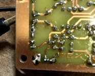
There is a pointer.
The DC servo has run out of correction range trying to get rid of the offset.
A DC coupled amplifier NEEDs
Remove the opamp. and check offset again.
The DC servo has run out of correction range trying to get rid of the offset.
A DC coupled amplifier NEEDs
There should be detection of excessive DC offset and speaker isolation and/or input muting.other ancillaries are required to maintain reliable operation.
Remove the opamp. and check offset again.
- Home
- Amplifiers
- Solid State
- 100W Ultimate Fidelity Amplifier