Yes 2N3773/2N6609 can be use for AX14
That's Great! Thank you Mr. Miles..
Regards,
😀 Hi mister apexaudio!
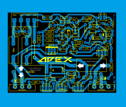
I like you AX-14 model and I want it to try it so I copy the layout and save it here is well I hope there are no errors lol. also the file if some one want it to look at it here is, and the software I use is Sprint Layout 5.0.
Regards
Juan
Hi Juan,
Very nice PCB. Do you have the bottom layout? Can you make the resistor spacing wider so it can accomodate Vishay RN60 series resistors.
Thanks.
Rey
Vishay RN60 series resistors
Well I'll check let see do you mean make the resistor longer or wider? I'm a bit confuse here lol. 😀 you mean the 5W ones? the R33 5W silkscreen is 22MM x 9.52MM size
Regards
vargasmongo3435
Well I'll check let see do you mean make the resistor longer or wider? I'm a bit confuse here lol. 😀 you mean the 5W ones? the R33 5W silkscreen is 22MM x 9.52MM size
Regards
vargasmongo3435
Attachments
Last edited:
Well I'll check let see do you mean make the resistor longer or wider? I'm a bit confuse here lol. 😀 you mean the 5W ones? the R33 5W silkscreen is 22MM x 9.52MM size
Regards
vargasmongo3435
I was referring to 1/4w resistor with L=10.8mm and W=3.68mm. The present PCB it is to tight to be accommodated. Also the elco it's to small can we increase it to 8-10mm. Thanks.
Rey
oh ok let see what can I do I also was making the tracks a bit wider so to avoid track burn out after replacing components ok I'll check man
Regards
vargasmongo3435
Regards
vargasmongo3435
OMG! I guess I have to check pith distance of components and sizes ok this is going to take some time as soon I got I posted.
Regards
vargasmongo3435
Suggestion: First, make a BOM using known parts (Vishay, Elna, Panasonic FC, etc...) taken from Mouser or Digikey catalogs. Next, take dimensions from their datasheets. Finally, draw their correspondent macros. Enjoy. 🙂
Regards.
Last edited:
Nice well I guess I have to check in Digikey good stuff!
Regards
vargasmongo3435
Hi Juan,
Yes the cap is bigger. I used 10uf non-polar Nichicon-72633 8X11.5mm from Partsconnexion.
Hi Mile,
I have done the above substitution of your AX-14. Is this correct? I am now testing it wtih your original PCB design and the sound is very good.
Thanks to both of you.
Regards
Rey
Last edited:
Do you mean from mister Apex layout?
Hi mister presbel
Did you mean mister Apex's original layout or the one I did a few days ago? this one: if no is ok. I'm just happy for what I'm doing.
Regards
vargasmongo3435
Hi mister presbel
Did you mean mister Apex's original layout or the one I did a few days ago? this one: if no is ok. I'm just happy for what I'm doing.
Regards
vargasmongo3435
Attachments
Last edited:
I have made my AX-14 before you have shown your design but I like your design and I know you can do something to accommodate the parts I like to use. If you can make the revision of the PCB I will try it with my parts. I will also try to replace the elco input with film of lower value and see the difference in sound.
Regards,
Rey
Regards,
Rey
AX-17V2
What is the AX-17V2 ?
It is a pdf attached to post 1391 .
The board says triple output though the AX-14 isn't so.
What is the AX-17V2 ?
It is a pdf attached to post 1391 .
The board says triple output though the AX-14 isn't so.
I suggest regularly that every PCB have all capacitor locations with multiple pin pitch options. This is to allow for different capacitors to be used without having to scrap all your "standardised" PCBs.
Is true Andrew , just like Alex MM designs clever indeed, let see if today I can place the components with this measurements, L=10.8mm and W=3.68mm 1/4 resistors, 8-10mm that is from presbel.
Regards
vargasmongo3435
Regards
vargasmongo3435
I did this one today not sure
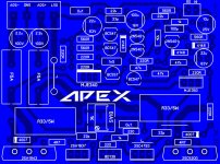
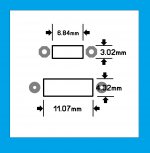
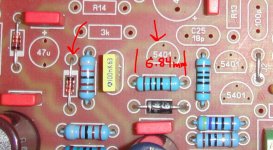
 I came out with this idea not sure still undecided, I think the resistor size is too big is about L-11.07mm W=4.02mm the first resistor is the one I use on my first board for other projects. the size of the resistor made the board grow so I didn't like that much I will try later to see if a came out with something better. maybe I need a
  weeeeeujuuuuuuuuuu!
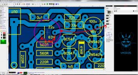
2.2uF 100V 8mm diameter
22uF 63V 10mm diameter
100uF 16V 8mm diameter
10uF 8mm diameter
Regards
vargasmongo3435
I came out with this idea not sure still undecided, I think the resistor size is too big is about L-11.07mm W=4.02mm the first resistor is the one I use on my first board for other projects. the size of the resistor made the board grow so I didn't like that much I will try later to see if a came out with something better. maybe I need a weeeeeujuuuuuuuuuu!2.2uF 100V 8mm diameter
22uF 63V 10mm diameter
100uF 16V 8mm diameter
10uF 8mm diameter
Regards
vargasmongo3435
Attachments
Last edited:
sorry, board sizes is 100mm width and 102mm height all the 1/4 watts resistors have that measurements L=11.07mm x 4.02mm that is why look so different.
Regards
vargasmongo3435
Regards
vargasmongo3435
sorry, board sizes is 100mm width and 102mm height all the 1/4 watts resistors have that measurements L=11.07mm x 4.02mm that is why look so different.
Regards
vargasmongo3435
I think it is already good but can you still adjust the 10uf input capacitor to accommodate up to 10mm pitch for film capacitor as suggested by AndrewT.
Hope I am not bothering you too much.
Regards,
Rey
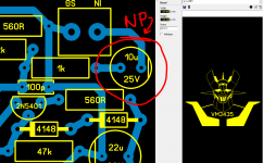
10uF 10MM pitch
Sure I can my friend it doesn't bother me at all just give me some time and I will make the caps for the 10uF input 10mm pitch to see how it looks, alright then.
that 10uF cap is suppose to be NP ?
Regards
vargasmongo3435
Sure I can my friend it doesn't bother me at all just give me some time and I will make the caps for the 10uF input 10mm pitch to see how it looks, alright then.
that 10uF cap is suppose to be NP ?
Regards
vargasmongo3435
Attachments
Last edited:
Sure I can my friend it doesn't bother me at all just give me some time and I will make the caps for the 10uF input 10mm pitch to see how it looks, alright then.
that 10uF cap is suppose to be NP ?
Regards
vargasmongo3435
Thank you for your time my friend. I decided to use Wima Capacitor 4.7uf 50V X 2 instead the 10uf elco. The dimension W=8.5 H=14 L=7.2 PCM=5mm. Is this possible?
Regards,
Rey
Well I'll check let see do you mean make the resistor longer or wider? I'm a bit confuse here lol. 😀 you mean the 5W ones? the R33 5W silkscreen is 22MM x 9.52MM size
Regards
vargasmongo3435
such functions 🙂
- Home
- Amplifiers
- Solid State
- 100W Ultimate Fidelity Amplifier