Was that the answer to what I asked?
he is telling you - AX14 (single paid of outputs) will work on 4-phm speakers with up to +/-35Vdc. You could push that to aroun +/-50Vdc with the 2-pair output version of the AX-14.
He is also telling you that your 4-ohm speaker will work fine with the AX-14, as long as you don't push past the limits by using too high voltage.
 Thanks Bullittstang!
 AX14 will work with +/-38V on 4ohms load without any changes.
Regards
+/-42V max for 8 ohms
+/-38V max for 4ohms
But you know your speakers impedance goes a little lower than 4 , so I suggested to stay around +/-35V to avoid to much heat dissipated on each output transistor.
2-pair output version is much more flexible .
oh the SR200? yes I do have it is a copy from Alex layout so please make sure is correct "those are the years where I was learning to use the software in 2013 😛
any chance you still have the dual output AX-14TP (protection) gerber or lay files? Having a hard time adding speaker protection off board, due to size constraints. Hoping this will work better.
Hello,
I have already built the P30 it is really excellent preamp .... I would also like to build this P30ZF, where can I buy these PCBs? thank you very much
... I renew my request ... if anyone can help me to preamp P30ZF, find layout or pcb ready ...
Thank you
Regards
... I renew my request ... if anyone can help me to preamp P30ZF, find layout or pcb ready ...
Thank you
Regards
Preamp.rar - Google Drive
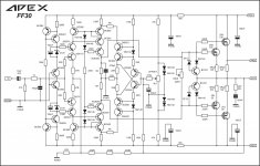
Here is an initial set-up and adjustment procedure for AX-14 which is applicable to any class AB amp generally. please edit and make it perfect so that Mr. Mile can put this in 1st post.
Please find below the procedure that is common to any class AB amplifier in general.
1. match the i/p transistor hfe to get low offset. (Q1-Q2)
2. for bias adjustment P1 is used.
3. Mount the VBE multiplier transistor on one of the o/p transistor with flying wires (Q10).
4. On first start-up, put a bulb limiter with a 50-60 watt bulb in series with the mains supply and leave it there for the first couple adjustments. Short your input connection and leave the speaker output open.
5. Bias is adjusted via P1. Keep it nearly in the middle position. apply power thro bulb tester and measure the voltage drop across emitter of Q14 and Q12.
Bias is given by= del V(Q14,Q12)/0.66 ohm (mA). bias current should be around 50-60mA
6. Measure the DC voltage across "speaker out" and "GND". It should be less than 30mV, ideally 5-10mV.
7. observe the bulb at all times. If its lights very brightly, then there is an issue with either a short or bias is too high.switch off everything and keep the pot P1 at zero and switch on again and observe.
8. measure the continuity between collectors of o/p to the heatsink. Then insulation is not proper if there is continuity.
9. If the bulb is not lit or dimly lit, keep turning the pot so that brightness increases slowly. Keep the bias to 50mA to 60mA.
10. If the bulb suddenly lights up very bright from off position while adjusting the bias, then there could be oscillation. Check the zobel resistor R26 for hotness. It should be cool. Hot means amp is oscillating.
11. if everything goes according to plan, then amp is ok and ready for test.
12. Switch off and remove bulb tester. attach a test speaker at output and connect the i/p to a source of music. play at very low volumes, listen for any hum /hiss. A hiss could mean, oscillation or cables are picking up some noise and passing it to the amp.
13.monitor heatsink temperature. , it shouldnt go beyond 50 Deg even at high volumes. Never operate the amplifier without mains slow blow fuse and also quick blow rail fuses. They are the first line of defense against any shorts or faults and will prevent the transformer from melting down.
Also never apply power unless output devices are securely insulated and mounted to a heatsink.
Hope this helps.
Hallo Prasi,
12. After you removed the bulb you first have to re-bias and adjust the dc offset before testing with a speaker.😉
The rail voltage will be higher when the bulb is removed.
12. After you removed the bulb you first have to re-bias and adjust the dc offset before testing with a speaker.😉
The rail voltage will be higher when the bulb is removed.
since the first start-up is initiated with small or no input signal,the difference between bias with and without test-bulb in series with primary of psu transformer will not be significant. it is not bad to re-check and re-adjust it after removing test-bulb, that's for sure.
what no one should do is to try test with high input load with connected output and with test-bulb in its place. that will show no real results, only the bulb will shy bright and the output signal will be distorted.
bdw,I had never had no trouble with start up with any of APEX designed amplifiers from the moment I have started them up and also never again while listening them,if I was to made them correctly from a first time. I made more than a dozen of them.
I try not to hijack here, but I have a question I get not the hang in.
I have done a amp, and did measure in sim, why is the distortion of VAS or input stage mucho higher then the output? is this feedback action?
I have a distortion with 1.6 amps of 0.000062 but the vas does 1.1 % and with 6 amp out I get 0.0012% and vas is 1.3% adcouse feedback does
push the preamp further into non linearity when correcting I think.
Does low be a go for high end? or get we a clinic amplifier, I think TIM/IMD is the biggest nogo, nasty sound you get with that.
Goodluck with this thread, very nice.
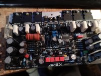

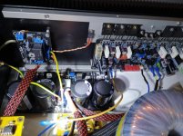
My F40
Is this A40? How does it sound? Bias and offset on it? Voltage you are using?


Is this A40? How does it sound? Bias and offset on it? Voltage you are using?
no it's the F40 that has a mosfet at the entrance
- Home
- Amplifiers
- Solid State
- 100W Ultimate Fidelity Amplifier