sure here 🙂 sprint file 6
Great job on the PSU design - instead of changing and re-routing the mosfets, wouldn't TIP31/32 been a decent replacement? I'm not sure, that's why I'm asking.
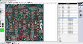
Also - any chance you have Lay file, or gerbers for the SR200 type of PCB design?
Great job on the PSU design - instead of changing and re-routing the mosfets, wouldn't TIP31/32 been a decent replacement? I'm not sure, that's why I'm asking.
Also - any chance you have Lay file, or gerbers for the SR200 type of PCB design?
since the original design works fine I didn't want it to change it too much,
oh the SR200? yes I do have it is a copy from Alex layout so please make sure is correct "those are the years where I was learning to use the software in 2013 😛
Attachments
Thanks - just starting to work with Sprint, so I will work through the schematic before ordering any boards.
How hard do you think it would be to shave 15-20mm off this board? maybe take the fuses and leds off and move the power connectors?
How hard do you think it would be to shave 15-20mm off this board? maybe take the fuses and leds off and move the power connectors?
Thanks - just starting to work with Sprint, so I will work through the schematic before ordering any boards.
excellent that is the way I do it schematic and verification 😉
Best regards
Juan
About the Apex A14, need some help
I have the boards from prasi
Matched the Q1-Q2 transistors HFE (158)
Amp is running but the voltage across Q12 and Q14 emitter differs ~25mv.
On Q12 i have 34mv across emitter
On Q14 i have 56mv across emitter
Prasi told me that to find the correct bias i had to divide the voltage across the emitter by 0.66. The correct bias for this amp is around 50-60ma. This way, i have 51ma and 84ma.
Guidance please.
Thank you all
The emitter resistors should be 0.33r, not 0.66. If you are measuring across them, you actually have 100 and 170mA of current.
I generally average them to safe figures, so put Q12 to 12mV and Q14 should be around 22mV and you will be fine.
Are your heatsinks getting hot? That’s the final judge of how much bias is too much.
I generally average them to safe figures, so put Q12 to 12mV and Q14 should be around 22mV and you will be fine.
Are your heatsinks getting hot? That’s the final judge of how much bias is too much.
The emitter resistors should be 0.33r, not 0.66. If you are measuring across them, you actually have 100 and 170mA of current.
I generally average them to safe figures, so put Q12 to 12mV and Q14 should be around 22mV and you will be fine.
Are your heatsinks getting hot? That’s the final judge of how much bias is too much.
Yes, .33r. Im measuring with one DMM lead on the emitter leg, and the other
at the ground.
is that correct?
You either go across both sides of the resistor (best way) - one probe on each side of the resistor.
If you can’t get to the resistor legs, you can go from transistor emitter to speaker output (one probe on each point)
If you can’t get to the resistor legs, you can go from transistor emitter to speaker output (one probe on each point)
You either go across both sides of the resistor (best way) - one probe on each side of the resistor.
If you can’t get to the resistor legs, you can go from transistor emitter to speaker output (one probe on each point)
Thank you, a lot
Im feeling so dumb! 🙂
Now i have the same value on Q12 and Q14.
I have to do some study on audio amps. 🙂
50mA is right in the middle you can go a little lower to 30mA but I wouldn’t go over 75mA unless you have a large heatsink.
Let me know how you like the sound- planning a build.
Let me know how you like the sound- planning a build.
If i raise bias, i raise output power? and Distortion?
I have big heatsinks. The ones from modushop 300x150mm
This amp is for bass duties on a Open baffle speaker arrangement with the sony vfet amp in dual mono for the full range drivers.
would you raise the bias on the AX14?
I have big heatsinks. The ones from modushop 300x150mm
This amp is for bass duties on a Open baffle speaker arrangement with the sony vfet amp in dual mono for the full range drivers.
would you raise the bias on the AX14?
Raising the bias does nothing for output power. If bias is too low it will cause distortion, but anything over 15mA should be plenty to avoid that.
I would go with 50mA and see how hot your heatsink gets after 30-45 minutes of music. You should be able to hold you hand on it for at least 3-5 seconds without discomfort. I have never had a reason to bias BJTs any higher.
It’s DIY so feel free to raise in small increments and see what you think, just keep a close eye one temperatures.
Hi..
I am going to pair up Apex Ax14 with 4 ohm Speakers which showing a dip in resistance around 500 hz upto 3.7 to 3.8 ohm.
My question is whether Ax 14 can drive these speakers comfortably or i might face some issues with the dip in resistance..
Please give your valuable opinions
Regards
I am going to pair up Apex Ax14 with 4 ohm Speakers which showing a dip in resistance around 500 hz upto 3.7 to 3.8 ohm.
My question is whether Ax 14 can drive these speakers comfortably or i might face some issues with the dip in resistance..
Please give your valuable opinions
Regards
Under +/-35V should be fine.
Was that the answer to what I asked?
- Home
- Amplifiers
- Solid State
- 100W Ultimate Fidelity Amplifier