Thanks Thimios. 🙂
The only thing screwed down are the power strip terminal blocks. It all changes often depending on what amp I want to listen to at the moment.
The only thing screwed down are the power strip terminal blocks. It all changes often depending on what amp I want to listen to at the moment.
All are fed from a 26-0-26VAC transformer. Measured without a load. Each are set to approximately +-24VDC.
The first three all measured about the same. Very low ripple. Surprisingly though, The PSU I built for my Self Preamp shows less noise and ripple than the first three. It shouldn't but it does. Not sure why.
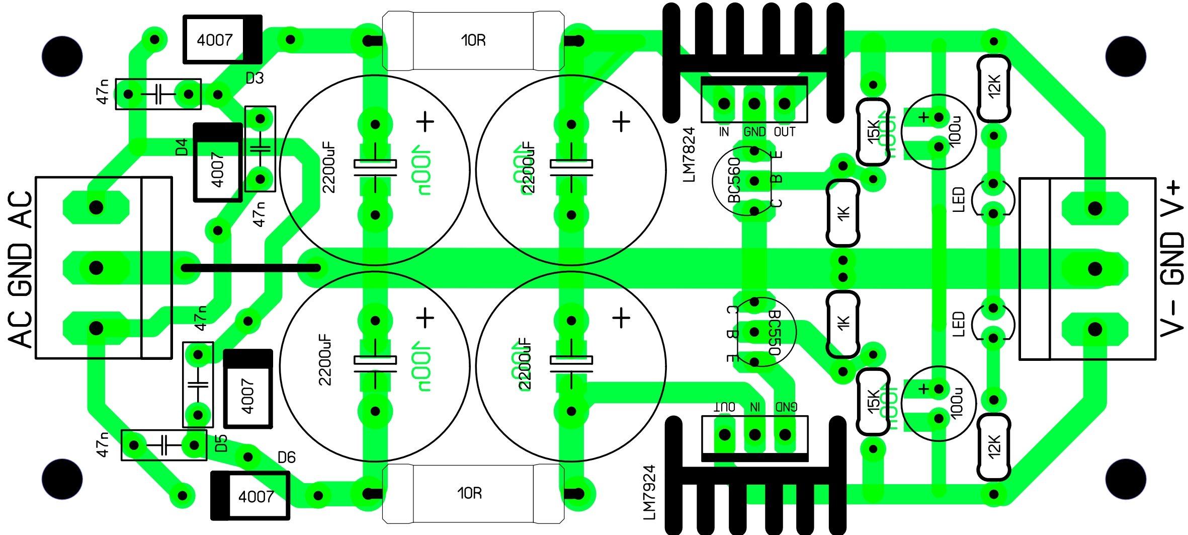
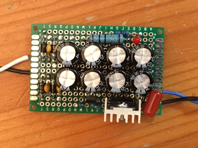
I just made one half of this on perfboard for 15v supply with a 7815 regulator. I only had 470uF caps so took 8 of them to make the PSU. I fit it on a 4cm x 6cm board though. Having the BC560 transistor control the ground reference seems to have added an offset though as the output measures 16.62v. Is that normal? The ripple as measured (no load) with DVM is 3mV.
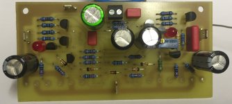
Top of board:
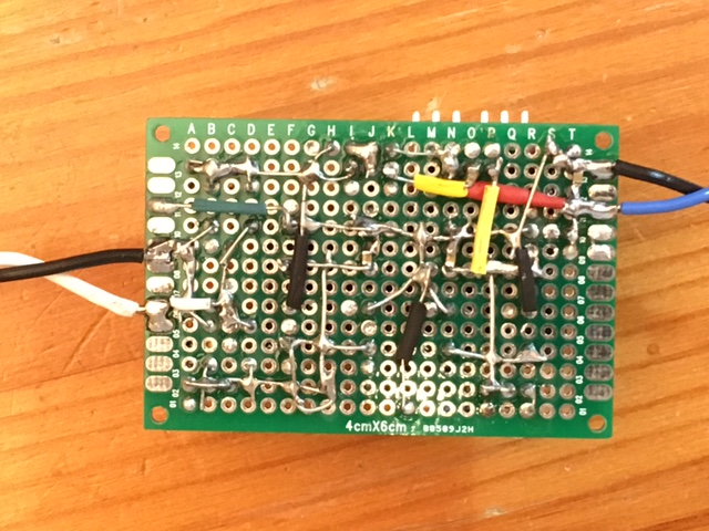
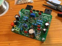
Bottom side (notice 100nF x7r SMT's between cap pins):
Attachments


Last edited:
Never give up...
Hi,
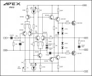
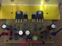
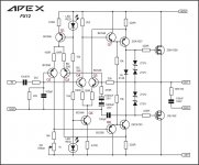
here is a new version of the FX12 with BC546/556 and 2 pairs. The first try was successful. +/- 28V rails for the test and 1 pair. The offset can be set with the potentiometer to zero. The sound is no different from the first version with 2SA970 / 2SC2240 and is very good. Quiescent current is 45 mA.
The next time I will going to use 40V and 2 pairs. Then I will switch to 50V.
@Mile: What should I change for it?
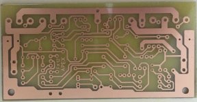
The layout is not really perfect (jumpers on the back). That's what I have to work on. But it's just a prototype 😀
regards
Olaf
Hi,
here is a new version of the FX12 with BC546/556 and 2 pairs. The first try was successful. +/- 28V rails for the test and 1 pair. The offset can be set with the potentiometer to zero. The sound is no different from the first version with 2SA970 / 2SC2240 and is very good. Quiescent current is 45 mA.
The next time I will going to use 40V and 2 pairs. Then I will switch to 50V.
@Mile: What should I change for it?
The layout is not really perfect (jumpers on the back). That's what I have to work on. But it's just a prototype 😀
regards
Olaf
Attachments
Hi,
here is a new version of the FX12 with BC546/556 and 2 pairs. The first try was successful. +/- 28V rails for the test and 1 pair. The offset can be set with the potentiometer to zero. The sound is no different from the first version with 2SA970 / 2SC2240 and is very good. Quiescent current is 45 mA.
The next time I will going to use 40V and 2 pairs. Then I will switch to 50V.
@Mile: What should I change for it?
The layout is not really perfect (jumpers on the back). That's what I have to work on. But it's just a prototype 😀
regards
Olaf
Nice work... no change for +/-50V. I will upgrade FX12 with DC Servo in next modification.
Regards
Hi,
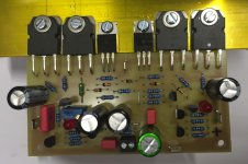
I tested 50 V (approximately 52V). The sound is incredibly good! Q1 and Q6 (see Image) are running hot and you can hear that 😀.
But you can touch the small Plastics for a few seconds without pain.
This voltage and 2 or 3 pairs and you can have a lot of fun!
regards
Olaf
I tested 50 V (approximately 52V). The sound is incredibly good! Q1 and Q6 (see Image) are running hot and you can hear that 😀.
But you can touch the small Plastics for a few seconds without pain.
This voltage and 2 or 3 pairs and you can have a lot of fun!
regards
Olaf
Attachments
I am sorry not posting earlier.
I have finished the modified circuit from this post:
http://www.diyaudio.com/forums/soli...imate-fidelity-amplifier-725.html#post4692495
It is working as expected with these: http://www.irf.com/product-info/datasheets/data/irf1407.pdf
I measured the impedance between both grounds:
Modified circuit 8x IRF1407: 0.0-0.1R (VC99 multimeter)
Non-modified circuit 4x IRF540: 0.2-0.5R(VCC99 multimeter)
For audiophile HIFI, go 8x IRF540
For robust design, ultimate shortcircuit protection, go for 8xIRF1407
These are facts.
It does not add HUM, anything at all to the output of the amplifier.
Does it change sound ? I have not been able to hear difference.
Thanks apex.
Attachments

Hi,
I tested 50 V (approximately 52V). The sound is incredibly good! Q1 and Q6 (see Image) are running hot and you can hear that 😀.
But you can touch the small Plastics for a few seconds without pain.
This voltage and 2 or 3 pairs and you can have a lot of fun!
regards
Olaf
Are you running one or two pairs of 2SK1058/2SJ162 with 52v?
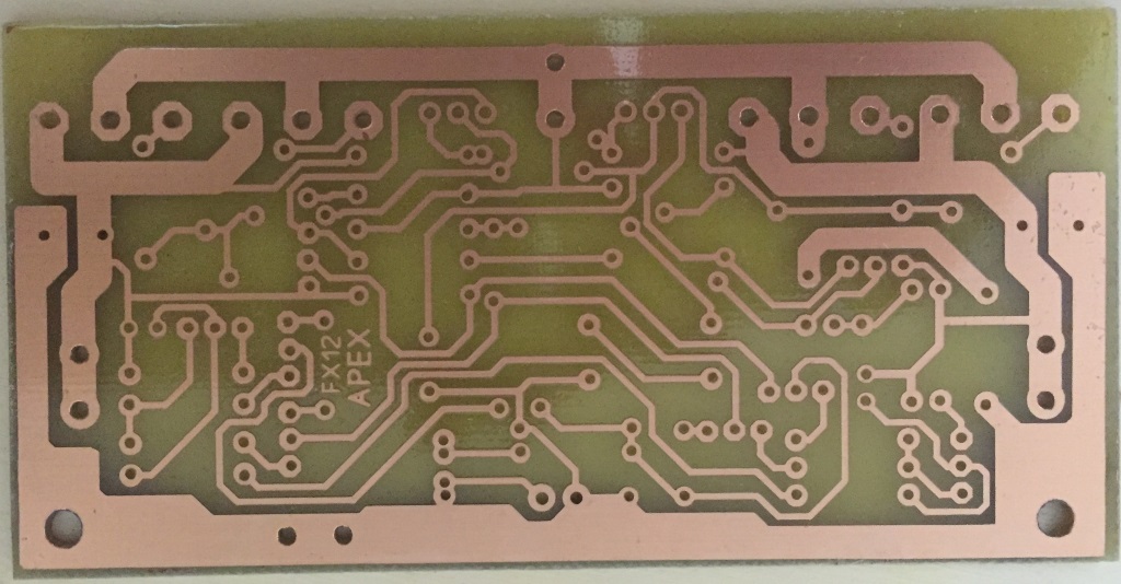
You do beautiful etching of the boards. Iron on Xerox or photosentive mask? Very nice boards

How does sound quality between FH9 and FX12 compare?
Last edited:
that look really nice I'm glad you like the layout 🙂
can you post more images of the complete board sir ?
Regards
Juan
Hi Sir Juan,
I'm not finished yet for complete six pairs of final transistor,
still waiting SMPS to support it, need more powerfull smps/psu to drive it 😀
will post a gain, if all finished
once again, thanks for the layout,
BR//
Made Sumber
Bali-Indonesia
Are you running one or two pairs of 2SK1058/2SJ162 with 52v?
You do beautiful etching of the boards. Iron on Xerox or photosentive mask? Very nice boards
How does sound quality between FH9 and FX12 compare?
Currently only one pair runs for testing. The parts are not cheap 🙂. The second pair I will assemble soon.
It is important to match the transistors (BC546/BC556) to get the amplifier stable and offset near zero.
The boards I do with photosensitive material. I'm doing this for years and have made the best experiences with this method. You can etch very fine structures.
I can not make a comparison with the FX8 or FX9, since I have not built the two. For FX8 I have a pair of boards. I will test it when I find time. But in comparison to other apex amplifier it sounds really good and is my faforite at the moment.
regards
Olaf
Just finished the second channel of FH9 HV. Waiting for another Pentium heatsink to arrive from eBay... This one went together fast.
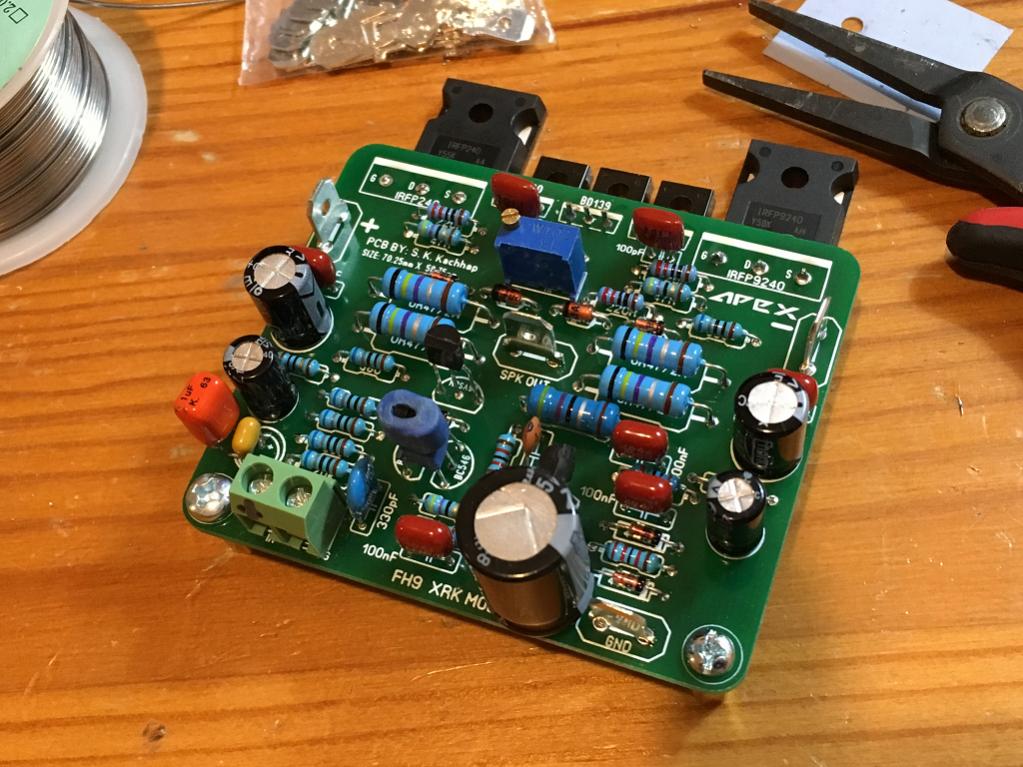
I am using IRFP's from Digikey for this one and noticed they look exactly like the ones from Aliexpress. Same markings, same quality of epoxy and fine satin finish on pins and heatsink tab. Digikey package says origin: China 🙂
I am using IRFP's from Digikey for this one and noticed they look exactly like the ones from Aliexpress. Same markings, same quality of epoxy and fine satin finish on pins and heatsink tab. Digikey package says origin: China 🙂
Attachments
I am sorry not posting earlier.
I have finished the modified circuit from this post:
http://www.diyaudio.com/forums/soli...imate-fidelity-amplifier-725.html#post4692495
It is working as expected with these: http://www.irf.com/product-info/datasheets/data/irf1407.pdf
I measured the impedance between both grounds:
Modified circuit 8x IRF1407: 0.0-0.1R (VC99 multimeter)
Non-modified circuit 4x IRF540: 0.2-0.5R(VCC99 multimeter)
For audiophile HIFI, go 8x IRF540
For robust design, ultimate shortcircuit protection, go for 8xIRF1407
These are facts.
It does not add HUM, anything at all to the output of the amplifier.
Does it change sound ? I have not been able to hear difference.
Thanks apex.
Nicely done rensli. A schematic of your modification imposed on APEX schematic would be useful to builders, I think.
edit: sorry I see you already posted. is that schematic as built version?
Last edited:
I am sorry not posting earlier.
I have finished the modified circuit from this post:
http://www.diyaudio.com/forums/soli...imate-fidelity-amplifier-725.html#post4692495
It is working as expected with these: http://www.irf.com/product-info/datasheets/data/irf1407.pdf
I measured the impedance between both grounds:
Modified circuit 8x IRF1407: 0.0-0.1R (VC99 multimeter)
Non-modified circuit 4x IRF540: 0.2-0.5R(VCC99 multimeter)
For audiophile HIFI, go 8x IRF540
For robust design, ultimate shortcircuit protection, go for 8xIRF1407
These are facts.
It does not add HUM, anything at all to the output of the amplifier.
Does it change sound ? I have not been able to hear difference.
Thanks apex.
Nice work.
Regards
That IRF1407 has some pretty amazing specs of 150amps and ultra low on state impedance of 0.0078ohms. Could it be used as basis of an OPS for audio or too slow?
I am still unclear how to add 8 of these for a speaker protection - can you please post revised/modified schematic?
I am still unclear how to add 8 of these for a speaker protection - can you please post revised/modified schematic?
Hi Sir Juan,
I'm not finished yet for complete six pairs of final transistor,
still waiting SMPS to support it, need more powerfull smps/psu to drive it 😀
will post a gain, if all finished
once again, thanks for the layout,
BR//
Made Sumber
Bali-Indonesia
I appreciated just take your time this is not a competition but a way of art and enjoyment "mostly a enjoyment" 😛 sometimes I spend weeks or even months before a power up a new project plus I read a lot jejejejejejeje 😛 good day sir
Best Regards
Juan
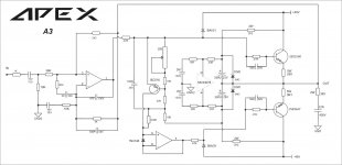
Apex Audio - very cool, 3 active devices (although cheating a bit as op amp has about a dozen transistors per amp, and Darlington is two, so technically maybe A29 in actual transistor count?) 😀
How does it sound?
How does it sound?
Apex Audio - very cool, 3 active devices (although cheating a bit as op amp has about a dozen transistors per amp, and Darlington is two, so technically maybe A29 in actual transistor count?) 😀
How does it sound?
This is only idea... there is A2 in this thread made by some members.
Regards
some progress
Hi,
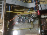
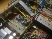
next stage FX12 - 2 pairs, +/- 50V. After 1 hour of music at bit more then medium volume the offset is still at 5 mV. The heat sink is hot, but still in the green area.
The photo of the back shows the "work in progress" 🙂
regards
Olaf
Hi,
next stage FX12 - 2 pairs, +/- 50V. After 1 hour of music at bit more then medium volume the offset is still at 5 mV. The heat sink is hot, but still in the green area.
The photo of the back shows the "work in progress" 🙂
regards
Olaf
Attachments

Hi,
next stage FX12 - 2 pairs, +/- 50V. After 1 hour of music at bit more then medium volume the offset is still at 5 mV. The heat sink is hot, but still in the green area.
The photo of the back shows the "work in progress" 🙂
regards
Olaf
Very nice thanks for raport about sound.
Regards
- Home
- Amplifiers
- Solid State
- 100W Ultimate Fidelity Amplifier