You mean the two BC546's sitting next to each other? My DMM's also have the hfe measurement holes on the top deck. How closely does it need to be matched? Should be easy as you say as they are made in the same batch probably when delivered (especially if bought on tape reel). I am new at making my own PCB's - for fabricating the PCB's with typical low cost Chinese suppliers (10 5cmx5cm boards for $10), do they accept the Sprint file directly? I have mostly heard that they want Gerber files.
Yes, Q1 Q2 (the ones near i/p connector). I think I was able to get within ~4-7. My DMM is an ordinary commercial type (only works with TO-92 devices 🙄)
If bought on tape, they may already be close enough, you may just need to confirm with DMM.
PCB: I think they would require gerbers, I am not sure. I had used eagle CAD and home etched the PCB's. Don't have experience with Sprint. May be Sonal or some one can generate gerbers and post here to help with your build.
P.S.:Terry had posted a link on transistor tester, I plan to get one too for my future needs.
Edit:
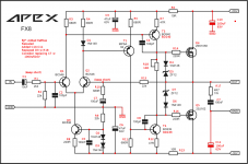
1.Gerbers, easy enough with sprint. attached.
2. use 1000uF16V for C7 as it tested better.
Attachments
Last edited:
First of all, I guess we need to see if the experts agree the layout is good to go and does not have any errors. But if someone could translate to required Gerber files that would be greatly appreciated. One more question - would it be OK to operate at +/-53v rails?May be Sonal or some one can generate gerbers and post here to help with your build.
Thanks in advance.
+- 53v is a little high for a single pair of outputs. If you assure that you will not go lower than 8 ohm speakers that may be OK.
Is that because the max current in the output MOSFET may be exceeded if impedance drops? So adding a second pair in parallel, and driving the gate via same signal can add more voltage (current) capability?
+- 53v is a little high for a single pair of outputs. If you assure that you will not go lower than 8 ohm speakers that may be OK.
+ one has to consider trafo regulation+ mains variation. In my place, sometimes its 230V and other times its more than 240V 😀😀😀. caps need uprating too..
I remember reading in VSSA thread that 45V is max for 1 pair latfets.
reg
Prasi
P.S. 1.Someone should check the sprint gerbers posted. I just did a basic export in sprint.
Last edited:
+ one has to consider trafo regulation+ mains variation. In my place, sometimes its 230V and other times its more than 240V 😀😀😀. caps need uprating too..
I remember reading in VSSA thread that 45V is max for 1 pair latfets.
reg
Prasi
P.S. 1.Someone should check the sprint gerbers posted. I just did a basic export in sprint.
That was not related to Lafet but to BC550/560 input pair => Vceo=45V limitation.
Marc
That was not related to Lafet but to BC550/560 input pair => Vceo=45V limitation.
Marc
Oh!, OK. Thanks for the same Marc.
reg
Prasi
Thanks for the Gerbers Prasi.
No mention. Pl see attached gerbers I have corrected the cap orientation on + rail, (and got some first hand experience in sprint!)🙂.
reg
Prasi
Attachments
Prasi,
Do you have a BOM with recommended tolerance and wattage for parts etc.? I am going to assume the latest Gerbers from Post 6509 are good as I just ordered the 10 boards for $10 from Seeed 😀
Thanks,
X
Do you have a BOM with recommended tolerance and wattage for parts etc.? I am going to assume the latest Gerbers from Post 6509 are good as I just ordered the 10 boards for $10 from Seeed 😀
Thanks,
X
Prasi,
Do you have a BOM with recommended tolerance and wattage for parts etc.? I am going to assume the latest Gerbers from Post 6509 are good as I just ordered the 10 boards for $10 from Seeed 😀
Thanks,
X
It was past mid-night when I last posted, so sorry for late reply. I never made a BoM, I used whatever I had, bought some that I didnt have.
Here are some suggestions based on sonal's layout.
1. All resistors to be 0.25W 1% MFR (except 4R7 zobel resistor which can be 1W or 1/2W metal/carbon film)
2. all 47uF caps to be 50V rated with 6.3mm dia. like I said before instead of 100uF/63V, use 1000uF 16V with ~8mm dia.
3. all 100pF caps to be ceramic MLCC CoG/NPO (generally these are the recommended types)
4. 12V zener can be 1/2 W rated.
5. trimmer to be 3296W type with 1k
6. i/p cap should be 10uF 25V, can polarized or NP. I used a nichicon muse NP, which I think should just fit on Sonal's layout.
7. rest can be read of the layout, so shouldn't be a problem, I think.
reg
Prasi
PS: ofcourse, these would hold good for the recommended supply voltages.
Last edited:
Thanks, Prasi. How is it that the 63v rated cap went down to 16v?
🙂 In the original sch by Mr. Miles, the voltage rating was not mentioned. So I had assumed 63V. Later to improve the 50Hz response (based on Terry's testing, Mr. Miles suggested to use 1000uF 16V (which incidentally have same pitch-keltron make), so there was no need to make any changes in layout.
Last edited:
Prasi,
Do you have a BOM?
Thanks,
X
I put one together, but I didn't have Prasi's recent recommendations. I also added Prasi's ref des to the schematic, and tightened it up a little graphically.
(Apologies to Mile)
Attachments
I put one together, but I didn't have Prasi's recent recommendations. I also added Prasi's ref des to the schematic, and tightened it up a little graphically.
(Apologies to Mile)
quite detailed, nice. But please check again. Just had a cursory look and here are my comments.
1. item 24,25 should be BD's.
2. item 22 and 22A, should be same. just bend it where you require depending upon pitch. no need to order separate part nos.
3. item1. C1. 25V is enough. I used nichicon muse NP here (I like it). since it is in signal path, should be of good quality.
4. item 11. the PCB is meant for an ordinary terminal block with 5.08mm pitch. 3 pin terminal block on Sonal's layout. Not too sure how to you would fit a RCA phono connector, unless you are panel mounting it somewhere and running wires directly to PCB.
5. R18, I used ordinary bourns 3296W 1k Multi Turn. It is set at 270ohm on 1 ch and 285ohm on another. It may still be fine with your proposed 500R
reg.
Prasi
P.S. Please check the diameters and ratings again as per Sonal's layout
Last edited:
i was able open it with MS excel 2013. It gave a bunch of warnings, I ignored.😛How do I look at the BOM? What file format is that?
How do I look at the BOM? What file format is that?
I started to write an explanation, but why? OpenDocument Spreadsheet
Excel will read and write it, as will Open Office, of course. If you don't have any spreadsheet software, simply download OpenOffice.
I'll implement Mr Prasi's changes (Thanks!) in the morning and upload a new revision.
BF
First of all, I guess we need to see if the experts agree the layout is good to go and does not have any errors.
Thanks in advance.
Sonal is an expert in layout 🙂. He has helped me and others many times and laid out numerous amps/circuits here in this thread and elsewhere. Just thought, I should let you know🙂.
- Home
- Amplifiers
- Solid State
- 100W Ultimate Fidelity Amplifier