Hi all, hi Ken & Geoffry,
I took the 60x60 prototype as far as i could after matching the conical throat to that of an XT1464 for the first 4cm, trying to make a little better transition. And then after relocating the 12" drivers over the ports a little more towards the throat, I felt I'd done all i could to the 60x60. Horiz polars had become nearly acceptable.
So I moved back to the larger 60x40, incorporating the same throat modification and 12" cones relocation. Uhg....60x40 didn't improve as much from those changes as did the 60x60.
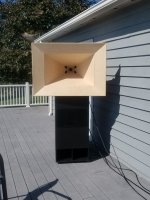
So, the last few days I bit the bullet and built the conical flare section that I'd been hoping to not have to add...simply cause every Danley synergy has the flare, as does BWaslo's speadsheet, I've heard about waistbanding ..and why do i think I can get away without it ?
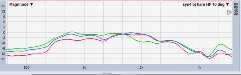
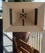
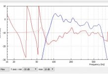
Pict is below...damn thing is getting big .... Anyway, the flare hasn't changed the oscillating polar response all that much.😕 10 degrees off axis still remains the center point around which response bounces around. You can see that in the first trace below, which is the lower section of the dcx464, which I'm wanting to use 650-3000Hz. Raw curves. Blue is 10 deg. Green is OA. Red is 20 deg.
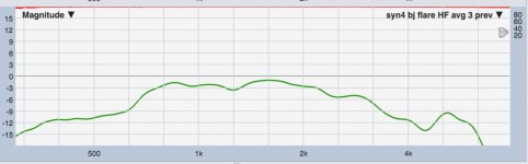
Next trace is the raw curve of those three averaged.
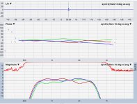
And last trace is processing built off that average trace. Processed curves. Same blue is 10 deg. Green is OA. Red is 20 deg.
Plenty of oscillation still. But it's sounding pretty good. I guess the real question I'm trying to figure out is, does the benefit of acoustic co-location override the issues that come with straight sided conical horns.
That and continued learning on how to improve the port design / driver location to minimize issue...
Oh, one thing that's helped and I have no real idea why other than a guess...I switched back to the bms4594he because the b&c's crossover at 3kHz appeared to be compounding polar oscillations. Man, these synergies are work !
I took the 60x60 prototype as far as i could after matching the conical throat to that of an XT1464 for the first 4cm, trying to make a little better transition. And then after relocating the 12" drivers over the ports a little more towards the throat, I felt I'd done all i could to the 60x60. Horiz polars had become nearly acceptable.
So I moved back to the larger 60x40, incorporating the same throat modification and 12" cones relocation. Uhg....60x40 didn't improve as much from those changes as did the 60x60.
So, the last few days I bit the bullet and built the conical flare section that I'd been hoping to not have to add...simply cause every Danley synergy has the flare, as does BWaslo's speadsheet, I've heard about waistbanding ..and why do i think I can get away without it ?
Pict is below...damn thing is getting big .... Anyway, the flare hasn't changed the oscillating polar response all that much.😕 10 degrees off axis still remains the center point around which response bounces around. You can see that in the first trace below, which is the lower section of the dcx464, which I'm wanting to use 650-3000Hz. Raw curves. Blue is 10 deg. Green is OA. Red is 20 deg.
Next trace is the raw curve of those three averaged.
And last trace is processing built off that average trace. Processed curves. Same blue is 10 deg. Green is OA. Red is 20 deg.
Plenty of oscillation still. But it's sounding pretty good. I guess the real question I'm trying to figure out is, does the benefit of acoustic co-location override the issues that come with straight sided conical horns.
That and continued learning on how to improve the port design / driver location to minimize issue...
Oh, one thing that's helped and I have no real idea why other than a guess...I switched back to the bms4594he because the b&c's crossover at 3kHz appeared to be compounding polar oscillations. Man, these synergies are work !
Attachments
What can I write with any confidence? Not much. If I follow your posts, the work you've done to get the throat right has helped the sound a lot, which makes sense.
That leaves the ports. Possibly having the ports in the corners would help (perhaps that's not an attractive proposition). Having them on the short sides, indeed dominating those sides as seen in the front view, must cause a signigificant impedance change and reflections. Whether the reflections and excitation of HOMs are sufficiently audible to require correction is up to you.
Myself, I've decided not to attempt another conical MEH - your construction skills appear somewhat beyond mine, and I'm reminded how much work it can be.
Ken
Did you see Mabat's work here Acoustic Horn Design – The Easy Way (Ath4) ?
The consequences of the defect added to that model might be of interest in considering the consequences of the relatively large ports (even by guessing an extrapolation to compare with your measurements, considering the port locations and the frequency response ripples).
Remember to make allowance for true effective source location of the wave in the compression driver which might not be at the plane of the throat (you can check by looking for lambda/4 reflections/dips).
Ken
Hi Ken, yes Mabat's work is amazing. And thx for your continued comments
I really don't know how to assess the response anomalies in what the straight sided walls are causing vs what the ports are doing. (to the coax CD response).
I did measure the CD on the 60x60 before putting any ports in, and it had the same flip flop in the 1kHz and 2kHz areas as the 60x40 does with ports.
In fact, that has been one constant with both horns and both CD drivers..... 10 deg off axis is the best center response with patterns oscillating oppositely on either side of 10 deg. Direct on-axis has been hardest to work with.
That said, yesterday I revisited foam strips, since I have added the last big unknown factor...the horn flare. I started with the horn flare off and found something I hadn't tried before...vertical strips of foam on the mouth edges to have a major positive impact on on-axis smoothing in the 1-2kHz range. However, horizontal strips on the mouth destroyed response confused: Thin strips running in the center of the horizontal horn section, mouth to throat smoothed 3-4kHz. Then I put the horn flare back on, with the foam strips in place, and response was slight worse. So I re-tuned, and even then response wasn't quite as good with no flare. That is encouraging because I'd love to skip the flare entirely.
Again, most all the trouble has been with on-axis vs everywhere else. So these strips represent bringing on-axis into line without messing up off-axis too much.
Anyway, pic of strips is below. It's given the best polars to date, and I switched back to the dcx464 for a looksee and the foam strips helped it even more than the bms. So I built dcx tunings from averages of OA, 10 deg, and 20 degs .... which worked nicely. Been listening this morning and for first time I'm not fighting tonal balance track by track more than the normal variances expected. Fingers crossed 🙂
Attachments

Mark,So, the last few days I bit the bullet and built the conical flare section that I'd been hoping to not have to add...simply cause every Danley synergy has the flare, as does BWaslo's speadsheet, I've heard about waistbanding ..and why do i think I can get away without it ?
Anyway, the flare hasn't changed the oscillating polar response all that much.😕
Processed curves. Same blue is 10 deg. Green is OA. Red is 20 deg.
Plenty of oscillation still. But it's sounding pretty good.
I guess the real question I'm trying to figure out is, does the benefit of acoustic co-location override the issues that come with straight sided conical horns.
Post #45 and others have ample references to the fact that the "oscillating" polar response issues are not going to be eliminated by any detail work you perform on the straight sided conical horns.
The benefit of acoustic co-location in a multiple entry horn does not preclude using horn designs that don't have the issues that come with straight sided conical horns, but designing and building large curved horns for one-off use is a lot (like +10dB) more work.
You don't mind all the work, time to get a couple buckets of Bondo-Glass, and "get 'er done" 😉
My playback preference probably would be smooth horizontal response with vertical response dips from the driver spacing compared to the conical horn response...
Hot Rod 8” 2-Way PA/Studio Monitor
Cheers,
Art
Attachments

Yeah, reality is slow to set in with me...but I'm getting it...adding the flare has removed the remaining hopes and doubts have I fully tried.
I think I've pretty much hit a limit on getting the syn attempts any better...
....without breaking out the bondo-glass 😉
So, I'm about to set a PM90 next to the last syn pictured...about time to compare i think....
I think I've pretty much hit a limit on getting the syn attempts any better...
....without breaking out the bondo-glass 😉
So, I'm about to set a PM90 next to the last syn pictured...about time to compare i think....
Did it happen already? 😎So, I'm about to set a PM90 next to the last syn pictured...about time to compare i think....
Did it happen already? 😎
I've had them side by side indoors. They sound so dang close to each other, it's hard to draw any conclusions. I guess because i tune everything the same way.
I need to change the PM90 with HF950 to a PM60 with XT1464 (the box converts), to better match the syn 60x40 design.
And right now, the syn has the dcx464 and the PM90 the bms. Should change the syn to bms too for fairer box-to-box comparison. (Only have one dcx)
Then I need to set them up outside to critically listen.
I can say this though from the indoor 'not quite apples to apples comparison'...I'm pretty sure outside will show a track by track preference, one vs the other....which I almost take as a universal given for any two similarly specified, well designed, well tuned boxes.
Last edited:
@Mark: Cool! I can only imagine the PM90 and 60 sound awesome, with those high-end BMS coax drivers.
Anything you can say regarding the efficiency? In my head I still wonder if what we both tried to do with the mid/low entry points (get them as close as possible to the throat) is (too?) detrimental to the horn loading of the lowest regions we would like the Synergy horn to play. My measurements show a not too high LF efficiency... My three-way Synergy horns perform better in that aspect. Their LF entry points are more towards the mouth, thus improving the horn coupling of the LF drivers. Art seemed to have nailed it with his SynTripP design, though...
Anything you can say regarding the efficiency? In my head I still wonder if what we both tried to do with the mid/low entry points (get them as close as possible to the throat) is (too?) detrimental to the horn loading of the lowest regions we would like the Synergy horn to play. My measurements show a not too high LF efficiency... My three-way Synergy horns perform better in that aspect. Their LF entry points are more towards the mouth, thus improving the horn coupling of the LF drivers. Art seemed to have nailed it with his SynTripP design, though...
well its better to put the mid holes as far from the throat as possible while keeping the reflection null above XO, if you can determine that in a reasonable amount of time and effort.
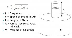
BTW, David McBean told me that the effect of the mid holes on the CD's passband is they act as helmholtz resonators, sucking energy out of the horn at frequencies determined by area and horn wall thickness. Using a calculator like
Helmholtz Calculator
may give you something to look for in the Synergy output. (haven't tried it for a single point ...)
Like you, I'm not surprised both horns sound so similar, given they were equalized the same. I expect the polar maps to be quite different and would be interested in seeing comparisons of them if you have the data.
@Mark: Cool! I can only imagine the PM90 and 60 sound awesome, with those high-end BMS coax drivers.
Anything you can say regarding the efficiency? In my head I still wonder if what we both tried to do with the mid/low entry points (get them as close as possible to the throat) is (too?) detrimental to the horn loading of the lowest regions we would like the Synergy horn to play. My measurements show a not too high LF efficiency... My three-way Synergy horns perform better in that aspect. Their LF entry points are more towards the mouth, thus improving the horn coupling of the LF drivers. Art seemed to have nailed it with his SynTripP design, though...
Glad you asked about mid/low sensitivity. I've been meaning to measure it, but output seemed in line with my other boxes using the same 12" rcfs, so haven't got there yey.
I just tried and learned you can't measure it indoors 😀 I get 105-6 dB 2V, 1 meter from mouth. (4 ohm nominal). Double checked it thinking I have to be doing something wrong, but no problems i can see...lot's of room adding in I guess...too high to be real. Pretty sure sensitivity is going to measure well when i get outside though 🙂
I do have a technique I like for measuring sensitivity, so I'll use this opportunity to describe it. I put pink noise on the driver with all processing in place. And measure the average rms voltage at the driver, and the average unweighted SPL from the mic.....over at least a one minute period. Then it's a simple matter to adjust the average SPL and voltage, vs distance, and equate it to the usual 1 watt at nominal impedance. (Although just giving voltage is obviously better.) I really like this method because it doesn't require an eyeball assessment of the response curve to quote sensitivity. (it will almost always be lower than the marketing quotes.) It is an integration through the intended bandwidth of the driver I think, and a very fair way to evaluate different boxes, particularly subs.
Anyway, off my soapbox ala 'me sensitivity method'.
I didn't end up with the ports as close to the throat as possible. I'm at 7" from throat. Oh, and I should say I measure the bee-line distance from port to throat. I was making a line straight out the center of the horn, calling that the distance, and going perpendicular from that line to the horn wall/corner. But I don't think that's the right way anymore.
The crossover and EQ curve in place for an acoustic 100Hz LR12 is below, to give a sense of boost being applied.
Attachments
Last edited:
well its better to put the mid holes as far from the throat as possible while keeping the reflection null above XO, if you can determine that in a reasonable amount of time and effort.
Well, Art Welter said that you have to place them as close to CD as possible.
What is right?
well its better to put the mid holes as far from the throat as possible while keeping the reflection null above XO, if you can determine that in a reasonable amount of time and effort.
BTW, David McBean told me that the effect of the mid holes on the CD's passband is they act as helmholtz resonators, sucking energy out of the horn at frequencies determined by area and horn wall thickness. Using a calculator like
Helmholtz Calculator
may give you something to look for in the Synergy output. (haven't tried it for a single point ...)
Like you, I'm not surprised both horns sound so similar, given they were equalized the same. I expect the polar maps to be quite different and would be interested in seeing comparisons of them if you have the data.
Thanks Jack,
Interesting, the Hemholtz CD suckout through the port holes.....
I'm not seeing how to apply the Hemholtz calculator though...any ideas?
I'll try to get polars for both boxes next time weather permits...
One conclusion I've come to, that I'd appreciate your thoughts on...
(and anybody else too of course)
For determining the notch frequency....
I've concluded it's from the 1/4 wave distance between acoustic origins, not throat-to-port distance. I think the CD origin is all the way to the diaphragm, we've seen this discussion before.
But I also think we have to look past the port all the way to the cone. the cone origin is all the way to cone.
I think 'all the way to the cone' means most likely close to the cone portion adjacent the dust cap.
This obviously gives a longer path than throat-to-port, but this longer path equates to where I keep measuring the notch.
Without moving the port, I watched the notch move down in frequency as I positioned the cone's outer perimeter over the port, and move up in frequency with the port more under the center of the cone. I'm led to believe minimizing port to cone center distance shortens the acoustic path....
Do you see any other factors / explanation for notch moving due to cone-over-port location?
So rightly or wrongly, I've decided I need to think about a synergy's acoustic centers from two different vantages:
From outside the horn, looking in from a distance, it seems apparent acoustic centers are the appropriate measure. Where the apparent centers have summed together to deliver at mic/listening position.
But inside the horn, where the drivers are interacting directly with each other, it seems actual acoustic centers of origin are what matter.
I know this is just a way of repeating of what I concluded above, with regard to notch distance...just thought it might help clarify my thinking (or lack thereof 🙄) a little..
I'll take a look at the fundamental equation later today. I think that will give an answer.
Very thoughtful discussion of reflection path length. Pragmatically, I would do a proto, measure and use the measurement to calibrate for the next iteration and my HR simulations. There is no doubt the soundpath path goes inside to a reflection surface but that surface might be a slitted phase plug rather than the diaphragm itself, depending on the construction of the CD. For my BMS4550s, it is the diaphragm because what you see looking behind the bug screen is a conical expansion back to the diaphragm. The effective distance I came up with from measurement for the 4550's was about 1 cm less than the 6.5 cm figure that one can find on the web for that driver, IIRC.
For other CDs, I expect to see a slitted phase plug some distance inside and I can't imagine sound not reflection off that surface, which is less than 10% open slit.
Regarding "all the way back to the cones" of the mids: (I didn't realize this until you made me think of it) The question is where does the reflected sound combine with the direct sound. Quantumdynamically, its at the observation point, the mic. So when you reposition the woofer over the port hole, you change the distance from the source to the mic so of course the path length distance changes. I'm guilty of having excluded the distance back to the mid cone in my path length calculations in the path. Likely that explains at least some of the difference between simulation and measurement that I've seen.
The distance will define the highest frequency which the mids will be able to reproduce before the reflection notch occurs. With a coax driver like the 4592 this becomes less of an issue, since this driver is able to play considerably lower than a 'normal' CD, thus it is possible to shift the mid/woofer ports towards the mouth.Well, Art Welter said that you have to place them as close to CD as possible.
What is right?
I came to the same conclusion during the prototype stage of my first synergy horn.I've concluded it's from the 1/4 wave distance between acoustic origins, not throat-to-port distance. I think the CD origin is all the way to the diaphragm, we've seen this discussion before.
I have to admit that I, like nc535, didn't think that far through, but you could very well be wright. This could imply a significant difference when using 10's or 12's. To be honest I didn't look into this with my second synergy design (the one you "copied"), but with my 3-way synergy I used small 4" midrange speakers that sit REAL close to the port, only 1 cm or so behind, which makes it less significant. But like I said, I didn't think of it...😱But I also think we have to look past the port all the way to the cone. the cone origin is all the way to cone.
I think 'all the way to the cone' means most likely close to the cone portion adjacent the dust cap.
Well, Art Welter said that you have to place them as close to CD as possible.
I believe it was BWaslo that said that, not Art Welter but he said it somewhat tongue in cheek. When you are struggling to get a synergy XO above 1.5 Khz, as he was in order to be able to use his favorite CD, it seems like that is what you have to do.
Regarding "all the way back to the cones" of the mids: (I didn't realize this until you made me think of it) The question is where does the reflected sound combine with the direct sound. Quantumdynamically, its at the observation point, the mic. So when you reposition the woofer over the port hole, you change the distance from the source to the mic so of course the path length distance changes. I'm guilty of having excluded the distance back to the mid cone in my path length calculations in the path. Likely that explains at least some of the difference between simulation and measurement that I've seen.
Well, I think I was confusing cd to mic path vs mid to mic path with mid direct to mic path vs mid back to cd and then to mic path when I wrote this. Clearly both mid direct and mid reflection paths start out with "mid cone to/thru mid port" sub-path and only then deviate. When you subtract the two path lengths, "mid cone to/thru mid port" sub path drops out.
When you reposition the mid cone over the port, ostensibly moving the cone back away from the port to center the mid over the hole, I would expect the time delay you need for time alignment between the mid and the CD to change but I would not expect the reflection null to move. If it does indeed move, then i would look for another explanation.
I believe it was BWaslo that said that, not Art Welter but he said it somewhat tongue in cheek. When you are struggling to get a synergy XO above 1.5 Khz, as he was in order to be able to use his favorite CD, it seems like that is what you have to do.
Thank you for clarification.
Well, I think I was confusing cd to mic path vs mid to mic path with mid direct to mic path vs mid back to cd and then to mic path when I wrote this. Clearly both mid direct and mid reflection paths start out with "mid cone to/thru mid port" sub-path and only then deviate. When you subtract the two path lengths, "mid cone to/thru mid port" sub path drops out.
When you reposition the mid cone over the port, ostensibly moving the cone back away from the port to center the mid over the hole, I would expect the time delay you need for time alignment between the mid and the CD to change but I would not expect the reflection null to move. If it does indeed move, then i would look for another explanation.
Hi guys, thx for thinking this thru with me..
I'm not following "When you subtract the two path lengths, "mid cone to/thru mid port" sub path drops out. "
I've been visualizing that the reflection is a roundtrip from cone, thru port to bounce off CD (wherever it bounces), then back thru port and back into cone. Which causes a half wave cancellation with easy to determine frequency because both paths are identical length. The measured notch appears to match physical distance pretty well afaict as I move cone around over port.
(That's how I came up with thinking cone center is close to junction of cone and dust cap.)
But, the same reflection after bouncing off CD, also goes straight out the horn, with a bit shorter path before it sums with cone output coming thru port and straight out of horn.
So I guess I'm trying to describe the two acoustic-center vantage points again.
One inside the horn, that uses true acoustic origins and causes cancellation at the cone before even leaving the horn.
And the second that uses apparent acoustic centers coming out of the horn, summing to cause cancellation out at the mic.
Two different cancellation frequencies I think, and I'm left wondering out to measure out which is which.
- Home
- Loudspeakers
- Multi-Way
- 100Hz two-way synergy project