'Stuff' happens. 🙁Wow, sorry GM………I hope my over enthusiasm didn‘t stress you out! Certainly wasn’t my intention 🙂
No, just 'life' has been happening faster than I can deal with it on occasion.
2) The 38" is predicated on a double layer of ~0.75"/1.8 cm bottom panels = 36.5" i.d., so if using 1", then 36" i.d. with 19.5" i.d. from the tweeter to the top plate = 56" or 55.5" i.d. height. Cross sectional area = ~232"^2, so width x depth is fine.2) Here’s what i’ve got for final dimensions (red, 8”) 12.5”X18.5”X57.5” I.D. = 217.9 L > 213 L (after subtracting drivers/horn displacement) 16” driver CTC / 38“ tweeter HT ………..correct?
3) lined/lightly stuffed from top down to just above port……..i suppose experimentation?
3) Correct, as it's been my experience that folks tend to over damp the various MLTLs I've designed from the get-go plus keep in mind that HR is pure math theory with no typical real world losses and last, but not least, most IME prefer a 'lively'/'toe tapping' performing speaker for all but those preferring the 'girl and a guitar' performance and/or some classical recordings.
Keeping the sanity is tough these days! Thank you for taking the time to answer so quickly 😎
Hopefully this storm (Nicole) doesn‘t cause you any compounded grief, its supposed to brush us (FL panhandle) and head north from there.
Everything is answered enough for me to start building it, but i do want to verify a couple things if possible. 🙂
1. Port location, 8.5” up from the bottom (I’m assuming thats I.D. bottom)…….is that measured to the center of the port?
2. Cross sectional area…….can width and depth be manipulated as long as comes out to 232”^2 ? I’m going to assume keeping depth the same or larger than width is preferable. Is there a ‘golden ratio’ (as they call it) for a straight mltl ?
Last edited:
You're welcome! Just needed a good night's sleep!
Yes, historically i.d. is the norm for any box/whatever design drawings, ditto the centerlines of a hole/whatever.
Correct assuming that what you put into it will fit! Note that it's a good plan to make cab depth ~1.5x the driver's installed depth.
Yes, a good plan if installed size constraints don't limit one's design too much, ditto horizontally offsetting the driver/vent on the baffle to average out its eigenmodes.
Well, any flat panel has eigenmodes; there's the golden ratio of course and many room ratios to choose from, though choosing a height for a TL is governed by acoustics, so for just width x depth or vice versa here's a few I've used.
1.1.14
1:1.17
1:1.25
1.1.26
1:1.28
1:1.41
1:1.45

Been building this in my head and it dawned on me a cabinet this big is going to need at least one central brace, is bracing (if made open as possible) a problem for this design?
So bracing won’t impact the TL performance? Was thinking horizontal 3/4” ply with spaced out 3“- 4” holes.
Virtually all the stress is vertical, so a ~ 56*0.707 = ~40" x 1x 3-4 board mounted on edge vertically and offset both vertically, horizontally using one of the ratios on the sides, back suffices. The top should have either a same-same board brace or double panel like on the bottom. A front/back brace tied to the top, rear brace, bottom plate and scalloped such as to allow preloading the woofers finishes it off plus doesn't reduce the cab's net Vb as much as typical 'holey' braces, not to mention much lighter too. 👍
Is there the opportunity to go with the flow?
Often the best orientation for a lot of boxes.
Picture pinched from the microTower planset, you can see the 2 braces. The boxes are small (7x7x30 external) so we get away with this scheme.
The braces run the same direction as the line. The holes are not necesarry from the TL part of the box but they complicate things for shorter frequencies that you would like to spend more time in the damping.
This also means they will follow the criteria of the subBrace having a higher aspect ratio than the panel it braces. And you want to avoid subPanels with equivalent sizes , sio first brace off centre.
Your big box will likely benefit from full-height braces. I like to brace thedrivers to the back of the box. This creates an i-beam like structure, greatly strengthening the baffle and distrubting energy that would light up a resonance to much more material. (i have a ton of drawings, and likely some better visualizations)
This is not a TL but it could be if it 2-3x taller, the braces would extend, would not impeded the TL flow, terminal at the bottom. Perhaps a bit overkill on this one (they are making it out of RichLite).

dave
This seems to be an accepted practice. Two panels equals twice the mass but much more than twice the stiffness, so the resonance goes up in frequency.I like to brace thedrivers to the back of the box.
That said, each case has different needs. Adding constrained layer damping may take some of the uncertainty out of it in cases where the result is uncertain when you build one off designs.
Why I use hardwood or no void plywood boards along with no void plywood box construction, drives the summed Fs at least an octave above the cab's pass band.
Lots of good info…..thanks very much!
In bracing the drivers to the back of the box are we looking to straight wood on magnet, or some sort of buffer between like 1/4” butyl rubber? I’m assuming the tension shouldn‘t be much more than a static fit?
Constrained layer damping is something i‘ve been looking at for awhile now, I might just make the box in a test form and if it works out wrap in a damping layer and then a nice outside layer for looks……weight is not really an issue as long as the weigh less than a fridge! 😎
With that small contact patch seems to me it would turn the back panel into a passive radiator of sorts?
On constrained layer construction does it negate the decoupling effect if you were to screw the inner panel to the outer panel (judiciously of course)?
On constrained layer construction does it negate the decoupling effect if you were to screw the inner panel to the outer panel (judiciously of course)?
No, both are in tension, though if the panel is stiff/rigid enough as it's supposed to be it's a moot point. 😉
Yes in that ideally the inner box 'floats' inside the outer box. In reality we normally are just damping each panel over most of its area and ideally only gluing the box together since any removable hardware is creating individual 'hot spots', so actual corner bracing is via glue blocks along ~71% of its joint to avoid making the corners a huge 'hot spot' and as crush zones in case it's dropped.
Yes in that ideally the inner box 'floats' inside the outer box. In reality we normally are just damping each panel over most of its area and ideally only gluing the box together since any removable hardware is creating individual 'hot spots', so actual corner bracing is via glue blocks along ~71% of its joint to avoid making the corners a huge 'hot spot' and as crush zones in case it's dropped.
Perhaps you meant can a fastener short circuit the damping, and it can if used a certain way because the two panels need free movement between them.
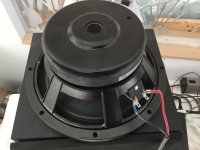
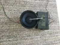
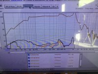
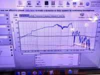
Heres the driver in question, there seems to be a 6db void between 50-60hz, ive included a pic of the measurement set up (its the best i could do with what i had, i‘ll get a better tripod soon) measured 3 times and it overlays the same.
Is this going to be a problem for the MLTL ?
and also is that hash above 600 going to be a issue, i planned on crossing at around 1.2k ?
Is this going to be a problem for the MLTL ?
and also is that hash above 600 going to be a issue, i planned on crossing at around 1.2k ?
Attachments
Last edited:
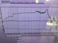
Here is a regular delta 10b measured the same way/same setup for comparison…….seems to have the same issues.
Attachments
Last edited:
- Home
- Loudspeakers
- Multi-Way
- 10” MTM design help