Haha, yeah, the wire is pretty thick and hard to manipulate but I'll give it a go. In case this becomes too cumbersome, what size of wire would be advisable for this application? Would it matter if it were stranded or solid core?
Stranded wire is theoretically the best because of better high-frequency performance. You will hardly notice the difference.
Solid core is difficult to bend around. I use AWG18 for power supply and speakers, AWG22-24 for signal wires.
Ok..... So um.... is "audio wire" different from "speaker wire"?
Audio cable is for me rather thin wires with a screen/shield. Speaker wire is from 0.75mm2 and upwards (no screen/shield).
Impressive English and clarity in writing.
Stranded wire is theoretically the best because of better high-frequency performance. You will hardly notice the difference.
Solid core is difficult to bend around. I use AWG18 for power supply and speakers, AWG22-24 for signal wires.
Audio cable is for me rather thin wires with a screen/shield. Speaker wire is from 0.75mm2 and upwards (no screen/shield).
Great, thanks! this helps immensely. Managed to find some speaker wire. Just have to find some shielded cables for the signal wires. 🙂
Thanks for the compliment! Much appreciated. You write really well too. Easy to understand especially for the likes of me.
So everything came in today (1 month wait - due to the virus, I guess).
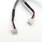
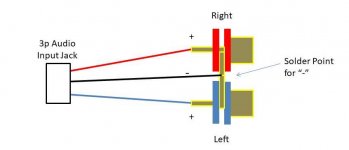
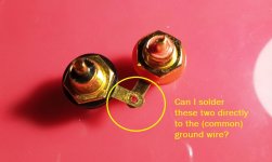
Quick question... Since the board has only 3 leads for signal input (L, R, Ground) and I'll be needing 4 (L, L Ground, R, R Ground), would it be OK to just use one wire for both L Ground and R Ground and solder said wire directly to the Ground terminal of both RCA jacks? Attached are pics for reference.
Quick question... Since the board has only 3 leads for signal input (L, R, Ground) and I'll be needing 4 (L, L Ground, R, R Ground), would it be OK to just use one wire for both L Ground and R Ground and solder said wire directly to the Ground terminal of both RCA jacks? Attached are pics for reference.
Attachments
My TPA3116 powered by 19V adapter fetches 2x18W to 8R max before distortion starts rising significantly (> 0.1%). IMO decent CAT5 cables (all pairs connected parallelly) is OK, I use them for this small amp. Plus the twisted geometry will reduce RF radiation from the digital amp and reduce noise pickup for sensitive speakers.
For input only shielded wire is suitable to avoid noise pickup. Either single shielded wire (coax), or two wires (stereo). Actually shielded CAT5 would do, but it is quite rare to have. If I could choose I would use separate coax for each channel.
I do not like the board as it has small SMD input coupling caps but not much to do with it...
What is your source (to avoid ground loop from regular PC output)?
Yes it would be OK.Quick question... Since the board has only 3 leads for signal input (L, R, Ground) and I'll be needing 4 (L, L Ground, R, R Ground), would it be OK to just use one wire for both L Ground and R Ground and solder said wire directly to the Ground terminal of both RCA jacks? Attached are pics for reference.

You can not only do it like this, it is the best way to ground the inputs!
If you use two ground wires, they form a loop the moment you plug in the source. This will catch all kind of noise inside the amp, mostly hum. As it is in the input, even very small induced voltages will be fully amplified.
If you use two ground wires, they form a loop the moment you plug in the source. This will catch all kind of noise inside the amp, mostly hum. As it is in the input, even very small induced voltages will be fully amplified.
What is your source (to avoid ground loop from regular PC output)?
i'll be using a usb dac/preamp. Maverick Audio D1. when would ground loop become an issue? what should be avoided?
You can not only do it like this, it is the best way to ground the inputs!
awesome, thanks!
This 2.1 amp has (3) flaws:
1 - The leftmost knob is the full range left and right gain. In the middle of the range it has a hiss, but not at the lower or higher end of the range. I keep it pretty high and adjust volume via the laptop and the main volume knob on the right as an acceptable workaround.
2 - When I connect it to power, 90% of the time, the turn on thump is so loud that it goes into protect and does not work. If I disconnect the sub channel, apply power, and then reconnect the sub channel it functions, but I understand there is a mute pin on the TPA3116d2 - has anyone tied into that in a simple manner to un-mute after a delay of ~ 2 seconds?
3- the output inductor gets dangerously hot. Only one of them. The 2nd from the right in the pic, which is one on the bridged sub channel. I have run this amp hard into a 1.6 ohm sub, but usually run it into a w5-1138smf 5.25" 4ohm subwoofer. Unsure if load changed temperature. It gets hot at idle/low and at high volume levels. The cheapo blue boards with SMT inductors do not get hot driving the same loads. Has anyone come across heat issues like this, and if so, has anyone replaced them with higher current rating inductors? These dont seem tiny so I am surprised they get so hot ( too hot to hold a finger on it, but not quite sear your flesh with a quick touch to check)
so TLDR;
Anyone replace output inductors because the originals got too hot
and
Anyone add a turn on mute to these boards?
Attachments
This is an amp, not a heater. It is class D which means high efficient, cool running. Ask your self, what do you win if you make the heater coil bigger?
There is a severe mistake in the construction of this amp that leads to in audible oscillation, which heats up the coil.
If you know how to use an ampere meter, you can see how much current it takes. Then compare to the data sheet.
This is, if you like playing with amps. An experienced amp builder can alter the construction to get rid of the problem.
If you only want to use such a module as an amp, throw it in the bin and buy one that is recommended in this forum.
By the way, you can not use such an amp outside of a metal case, for safety and EMF reasons. You probably don´t care, like most, I know. Depends on your country what happens if you run such an transmitter and disturb air traffic.
Wading through your condescension ( you okay buddy?) I appreciate the tip about it ringing. I have not much amp tinkering experience, hence playing with $5 modules and not expensive things. I will chase that a bit as only the sub channel has this, so it leads me to suspect the op amp input stage.
Member
Joined 2018
XH-M139 Issue
HI Jared-San,
This board has so much design & parts selection issues.
There are two root causes in XH-M139 Amplifire core heating.
1. Too easy magnetic saturate-able toroidal core inductors.
2. Small swing of slave clock signal.
In detail of this, you can see them in my Japanese web-page as follows...
Destop 2.1 channel Amprefire Modification
(Machine Translated)
Google 翻訳
This was a most terrible designed amplifier which I bought
Hope you can fix these issues before burn accident occur...
This 2.1 amp has (3) flaws:
1 - The leftmost knob is the full range left and right gain. In the middle of the range it has a hiss, but not at the lower or higher end of the range. I keep it pretty high and adjust volume via the laptop and the main volume knob on the right as an acceptable workaround.
2 - When I connect it to power, 90% of the time, the turn on thump is so loud that it goes into protect and does not work. If I disconnect the sub channel, apply power, and then reconnect the sub channel it functions, but I understand there is a mute pin on the TPA3116d2 - has anyone tied into that in a simple manner to un-mute after a delay of ~ 2 seconds?
3- the output inductor gets dangerously hot. Only one of them. The 2nd from the right in the pic, which is one on the bridged sub channel. I have run this amp hard into a 1.6 ohm sub, but usually run it into a w5-1138smf 5.25" 4ohm subwoofer. Unsure if load changed temperature. It gets hot at idle/low and at high volume levels. The cheapo blue boards with SMT inductors do not get hot driving the same loads. Has anyone come across heat issues like this, and if so, has anyone replaced them with higher current rating inductors? These dont seem tiny so I am surprised they get so hot ( too hot to hold a finger on it, but not quite sear your flesh with a quick touch to check)
so TLDR;
Anyone replace output inductors because the originals got too hot
and
Anyone add a turn on mute to these boards?
HI Jared-San,
This board has so much design & parts selection issues.
There are two root causes in XH-M139 Amplifire core heating.
1. Too easy magnetic saturate-able toroidal core inductors.
2. Small swing of slave clock signal.
In detail of this, you can see them in my Japanese web-page as follows...
Destop 2.1 channel Amprefire Modification
(Machine Translated)
Google 翻訳
This was a most terrible designed amplifier which I bought
Hope you can fix these issues before burn accident occur...
THANK YOU CyberPit !!!!
I removed C40 and the inductor temp is nowin line with the others, a reasonable temperature. You and your website did an excellent job of showing your diagnosis and the reasoning behind the repairs.
This is amazing that a fix that took 45 seconds to wait for the iron to heat up, and then 3 seconds to flip the capacitor off the board fixed things.
So I may have celebrated too soon. After some time, the inductor gets hot again. I do not have a fast enough scope to look at the timing signal sadly, but I think the STM32 scope kit might work well enough to tell me what the board is operating at. I will back burner this for a bit until I get the stm32 scope built.
Question: are you running any of the output channels without anything tied? (Are all channels connected)?
If any channel is disconnected, there's probably the reason to heat up so much (how you didn't fried something yet?)
If any channel is disconnected, there's probably the reason to heat up so much (how you didn't fried something yet?)
running 6 ohm satellites and a 4 ohm woofer.
It seems to be pretty hard to kill one of these chips. Another one I modded from stereo to mono shorted the output a few times.. it burned up the trace but still works fine. ( the - plane on the other board had a very tiny gap from the output terminal through hole pad to the plane. Soldering a jumper to it and leaving rosin was enough to get it to arc.)
It seems to be pretty hard to kill one of these chips. Another one I modded from stereo to mono shorted the output a few times.. it burned up the trace but still works fine. ( the - plane on the other board had a very tiny gap from the output terminal through hole pad to the plane. Soldering a jumper to it and leaving rosin was enough to get it to arc.)
I was asking because what can burn are the capacitors or inductors at the output because the speaker acts in the low pass filter applied and the chip doesn't like so much to be left "loadless"
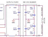
My I ask a question about TPA3116 and output filters.
At the output there is first LC filter and then C-RC snubber. Can this be the way around – first C-RC filter and then LC filter?
The problem is I have this TPA3116 amp with C-RC snubber but no LC filter. Can I just add LC filter after the C-RC snubber?
Regards
At the output there is first LC filter and then C-RC snubber. Can this be the way around – first C-RC filter and then LC filter?
The problem is I have this TPA3116 amp with C-RC snubber but no LC filter. Can I just add LC filter after the C-RC snubber?
Regards
Attachments
Member
Joined 2018
My I ask a question about TPA3116 and output filters.
At the output there is first LC filter and then C-RC snubber. Can this be the way around – first C-RC filter and then LC filter?
The problem is I have this TPA3116 amp with C-RC snubber but no LC filter. Can I just add LC filter after the C-RC snubber?
Regards
Hi Igla-San,
I guess your board is using Beads instead of LC-Networks. The Snubber circuit is mainly intend to dump the ringing of switching waveform. You can add LC-Filter post of them and the snubber-circuit after the additional LC reconstruction filter.
Then, you will get the cascaded reconstruction filters finally.
To tuning the snubber circuit, better to watch the ringing waveform with oscilloscope. (Of course loaded with actual speaker and Cut & Try is the best way for this...)
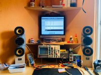
Just my humble workshop system, amp was € 7,50 plus X-over parts.
Speakers out of left over sewer pipe, drivers I had from salvaging old cabinets.
Just treat this amp as a tube amp to avoid excessive popping, therefore I added the switch in the middle to connect and disconnect the speakers.
L/R balance about 3 dB off, corrected that in the playback software.
I am happy with the result!
Attachments

- Home
- Amplifiers
- Class D
- TPA3116D2 Amp