hi, quick thought on this one. Selecting drivers for price and availability is important, but it seems to consume most time of people atm so your remark is true. However, in reality drivers come and go, and measuring is core activity for speaker builder. So, perhaps just select peerless and if it goes under someone will find alternatives. Active person could measure several drivers from the get go. With measurement data it's not too hard to recalibrate xo. Perhaps build and tweak with one set, and copy the response to others in simulator so a lot less of work.Few would WANT to re-measure and re-do a passive crossover due to supply issues...

Guys... I was under the impression the woofer choice is done, you sealed the deal. If you go in circles and keep questioning basic decisions about the design, this will never work out to a coherent result. You need to stick to your decisions so you can build on them in to the next steps.
Hi, reading this topic, I would like to add my 5cents. BTW very good discussion 😉
SLS12 - you can simply add extra bucking magnet to get better Q parameters, it will not cost a lot
Midrange - be carefull with 4 ohm speakers, you will need big capacitor. Maybe aim to 8-16 ohm with high sensitivity - it will allow to use smaller value C and thanks to higher sensitivity, you can also use air core L with higher resistance (=cheap).
Midrange 2 - choosing easy rollof one will allow simple (=cheap) crossover
Tweeter - consider waveguide version, speaker will be more prone to suboptimal room placement - and if you will be lucky, you can use just one C as tweeter crossover. Maybe rst28f + 148mm Visaton WG?
The design is not finalized until drivers are bought and delivered, and the wood for the first cabinet is cut... 🙂I was under the impression the woofer choice is done, you sealed the deal.
Even though it seems that a 10" option would be better from a technical or analytic standpoint, the 12" woofer does seem to capture the imagination of more people. A project that is going to appeal to many people needs to be appealing. Many people like the idea of a 12" woofer 3-way.
Playing around with some VituixCad simulations, I think that it will be possible to incorporate the +2 to +3 dB 100 Hz woofer hump into the voicing of the speaker. It will require that the midrange have a 2-pi sensitivity that exceeds the woofer 4-pi sensitivity including the +3 dB 100 Hz hump.
So my vote is to stick with the 12" SLS.
My vote is to stick with 12" SLS also.
But as I'm waiting for the 15W/ to be delivered and measure several drivers, I thought it was fair to address Zvu's points. And I really did want to know if Peerless availability in Europe was an issue, and it doesn't seem to be. (At least it is no more of an issue than everywhere else.)
But as I'm waiting for the 15W/ to be delivered and measure several drivers, I thought it was fair to address Zvu's points. And I really did want to know if Peerless availability in Europe was an issue, and it doesn't seem to be. (At least it is no more of an issue than everywhere else.)
Guys, Would like to know if we need to select in VituixCad the item " Show the effect of inductance" in the datasheet sims we publish here or elswhere or if it is needed just for the design ?
thanks.
thanks.
But, reading datasheet seem like 15W/4424 has a smaller VC 25 mm vs 32 mm and no alu ring in the motor...If you're going for the 15W/4434G00 as a pure midrange, why not choose the 4424G00 - shorter voice coil, higher sensitivity...
A smart design would include such x/o points and electrical order that none of the passive parts (type,values,cost) would present a problem.
The problem is prejudice (npe's , cement resistors, cored inductors, drive units without inductance reduction measures, no waveguide, sharp edges, Qtc around 1, all bad, etc.)
The problem is prejudice (npe's , cement resistors, cored inductors, drive units without inductance reduction measures, no waveguide, sharp edges, Qtc around 1, all bad, etc.)
Again, is the effect of inductance is selected, because when I selzct it the efficienty drops few dBs more in 4 Pi and the F3 F6 is climbing with 10 hz more circa.Nobody thought of a passive 3d order tuning for the 12” SLS?. What would be the cons except for the cost of a big (electrolytic) cap?
Nobody thought of a passive 3d order tuning for the 12” SLS?. What would be the cons except for the cost of a big (electrolytic) cap?
I have thought of all orders. I assume with the collection of smart people contributing, when we get all drivers selected and measured in a precise prototype cabinet we will get a good solution. There are always tradeoffs and a benefit of a group project is a single person won't make the final decision. I am quite confident that when we are done, this will be a high performing, good sounding, speaker.A smart design would include such x/o points and electrical order that none of the passive parts (type,values,cost) would present a problem...
Hey all, was just scrolling around on SB Acoustics website. And then I came across this Open-source kit they have on their website. A 12" monkey box, with a 4" mid and 1" tweeter. Maybe it's an inspiration for a design in this thread.
SB Acoustics - Gema open source kit
SB Acoustics - Gema open source kit
Last edited:
20mh coil and 470uf cap to squash low end peak? 😱 Although OSMC actually has something similar.
Was talked already about the Gema.
Why a 18 dB low pass for the SLS? It is flat long enough for a 12dB and a RC for impedance if needed?
Why a 18 dB low pass for the SLS? It is flat long enough for a 12dB and a RC for impedance if needed?
I promise we won't have a 20mH inductor in our crossover 😁20mh coil and 470uf cap to squash low end peak? 😱 Although OSMC actually has something similar.
20mh coil and 470uf cap to squash low end peak? 😱
We won't need any of such, if everything goes right.
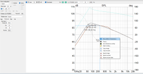
Okay, resistance is not futile, trues numbers even less, here 2 sim to illustrate my question (seems the SLS12 reacts better than the SB34RNXL to the "show effect of inductance" in Vituix option).
Which surprise me hence my questions is the F3/F6/F10 are moving up so less low end (2 Pi sim). With the SLS12 the option "effect of the inductance" move not too much the low end versus the SB34RNXL I made.
All is 2P w/o LP, brown difraction with F3/F6/F10 datas on screens . So behind 250 Hz (supposed to be the cross over cut off) remove -6 dB circa. so 83 dB sensivity at Pi 4 full space
Notice the parameters for the baffle and datas (distance of walls, etc).
How please, you guys do your sim from T&S ? With or W/O the "show effect of difraction" and how do you add still in the sims the effect of the coil inductance for the low pass at chosen crossover ? Do you need to swap into the filter making screen, so have measured your speaker already ?
Are those sims correct according to you ? (SLS12- Qtc 0.77 - 70 L w/o LP filter : F3 : 49 Hz F6 : 39 Hz - sensivity 4Pi at 100 Hz : 82.6 dB)
This is with the former datasheet, the new is said 2 dB less. Don't know which ones are on the shelves everywhere?!
So sensivity of mid around 250 Hz is around 2 to 3 dB loss after difraction, so minimum sensivity of the mid needed 85,6 dB/2.83V ? (more if resistor in serie or air coil with Dcr)) ?
Thanks
Attachments

Last edited:
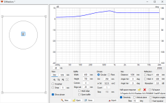
I always set the Z1k/10k in the T/S parameters

"Show effect of inductance" always checked
Qa = 5 (full stuffed) for closed box / Qa = 20 (stuffing only on the wall) for BR
Set the driver in the actual position on the baffle and export the diffraction responses at 10m for the low freq. part and at 1m for the high freq. part.

You should get something like this

STATISTICS
f3 48,3 Hz
f6 38,9 Hz
f10 30,4 Hz
Zmin 5,9 Ohm @ 5 Hz
Zmax 34,3 Ohm @ 50,4 Hz
GDmax 5,7 ms @ 47,6 Hz
XmaxC 1,1 mm @ 5 Hz
Pmax 1,4 VA @ 5 Hz
-------------------------------------------------------------
DRIVER: Peerless SLS-P830669, 1 pcs in series
n0 0,69 % Reference efficiency
SPL 90,5 dB/W Sensitivity
USPL 92,1 dB/2.83 Sensitivity
EBP 54,3 Efficiency bandwidth product
Dd 25,8 cm Effective diameter of driver
Vd 433,9 cm^3 Maximum linear volume of displacement
Cas 9,43E-7 m^5/N Acoustic equivalent of Cms
Mas 2,71E1 kg/m^4 Acoustic equivalent of Mms+Mme
Ras 7,57E2 Ns/m^5 Acoustic equivalent of Rms
Rae 9,22E3 Ns/m^5 Acoustic equivalent of Re
-------------------------------------------------------------
BOX REAR 1: Vb=84,8 l, Ql=100,0
Fb 50,5 Hz System resonance frequency
Cab 6E-7 m^5/N Acoustic compliance of air in enclosure
Rab 1,05E3 Ns/m^5 Acoustic resistance due to absorption
Ral 5,25E5 Ns/m^5 Acoustic resistance due to leakage
Qtc 0,75 Total Q factor
"Show effect of inductance" always checked
Qa = 5 (full stuffed) for closed box / Qa = 20 (stuffing only on the wall) for BR
Set the driver in the actual position on the baffle and export the diffraction responses at 10m for the low freq. part and at 1m for the high freq. part.
You should get something like this
STATISTICS
f3 48,3 Hz
f6 38,9 Hz
f10 30,4 Hz
Zmin 5,9 Ohm @ 5 Hz
Zmax 34,3 Ohm @ 50,4 Hz
GDmax 5,7 ms @ 47,6 Hz
XmaxC 1,1 mm @ 5 Hz
Pmax 1,4 VA @ 5 Hz
-------------------------------------------------------------
DRIVER: Peerless SLS-P830669, 1 pcs in series
n0 0,69 % Reference efficiency
SPL 90,5 dB/W Sensitivity
USPL 92,1 dB/2.83 Sensitivity
EBP 54,3 Efficiency bandwidth product
Dd 25,8 cm Effective diameter of driver
Vd 433,9 cm^3 Maximum linear volume of displacement
Cas 9,43E-7 m^5/N Acoustic equivalent of Cms
Mas 2,71E1 kg/m^4 Acoustic equivalent of Mms+Mme
Ras 7,57E2 Ns/m^5 Acoustic equivalent of Rms
Rae 9,22E3 Ns/m^5 Acoustic equivalent of Re
-------------------------------------------------------------
BOX REAR 1: Vb=84,8 l, Ql=100,0
Fb 50,5 Hz System resonance frequency
Cab 6E-7 m^5/N Acoustic compliance of air in enclosure
Rab 1,05E3 Ns/m^5 Acoustic resistance due to absorption
Ral 5,25E5 Ns/m^5 Acoustic resistance due to leakage
Qtc 0,75 Total Q factor
Attachments
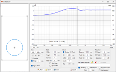
thanks. So it gives also a tip to add the effect of a 6dB serie low pass inductor if we cheat with the 1K windows... Cool ! At least an aproximation.
You setuped the distance at 10 meters (10 000 mm) ? What is the 1 dB absorption in the low end ? But 10 meters, should we put here instead the max deepness of the listening room ?
I simmed at 0.60 meters from the front wall (with the front baffle assuming the deepness of the cabinet not being more than 40 cm )!
Ah, I layouted the woofer at the wrong heigth for the project...
I will try to make a spl file made from the sim of difraction to make an artificial filter from those datas to see how react the low pass of a 12 dB or more for that woofer.
Last edited:
- Home
- Loudspeakers
- Multi-Way
- Budget Classic 3-way Discussion Thread