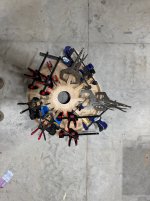
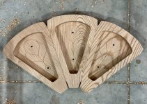
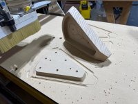
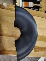
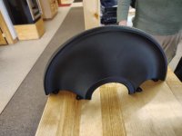
I have been CNC'ing the petals for my horn virtually non-stop - I knew this was an excessively laborious project, but man-o-man I'm giving my CNC a workout. Here's a pic of a dry-fit of the back-half of each petal to verify that the miter angle was right (looks like I got lucky!). I still have to fabricate all the front-halves of each petal and glue them up before I glue up the horns. Each petal is 2 pieces; each piece is probably 2+ hours of CNC milling and there's 20 of them (9 per horn + a couple extras for my inevitable screw-ups). All in all, it is probably 100+ hours of CNC work. However, the results so far are promising at least aesthetically. I'm not particularly worried about their acoustical performance - from what I've seen above I'm sure it will sound fantastic.
Attachments


Hi bmc0,Well, I was curious so here's some data anyway. I used Hornresp to calculate a profile that hopefully isn't too far off (265Hz; T=0.71; "Exact Profile" selected on export), then used ABEC3 for the simulation.
Thank you for the initiative, appreciate it! If my perception is correct, I see different directivity curves in respect to different rotation axes (z-axis on throat versus z-axis on mouth) and mic distances. My measurements look like something between picture 3 and 4 (mouth ref). Fyi, for my horn curve, I used the original Le'Cleach xls spreadsheet -not Hornresp- and 3D modeled in Blender to be able to print it. I think your curve is close enough to show the effects of how you measure directivity on my horn. IIUC there is not really a golden standard to compare sims with actual measurements and if you don't know those parameters of the sim that were used, you may end up with differences between the model and the measurements. Am I correct?
Feels like it’s screaming to be a MEH down to 80hz 😅It could be square I guess but intuitively, it's probably better to make it just a bit rectangular.
This is the current "dev version 0", BTW (306 x 252 mm, maybe too deep):
View attachment 1423532View attachment 1423537
View attachment 1423533 View attachment 1423534
View attachment 1423535 View attachment 1423536
Where you guys crossing over these horns?
I have woofers that don't break up till 1200hz and I see that the ATH horn and my SB ROSSO-65CDN-T is designed for 645hz.
So I have a lot of flexibility here. I'm also using Joseph Crowe's back cups that are supposed to lower the 65cdnts Fs down to 470hz.
Im running the hypex plate amps so i can do any slope and any time delay at any frequency easily. I guess I want the woofers to be basically out of the picture before 1200hz so I guess I can do a nice gentle slope in the middle and have no stress on either side.
2nd order at 900hz might be the go? The lower I go the more 'point source' the sound will be. At the risk of over driving the open back cupped 65cdnts
That sounds reasonable to me, and I think you could go even lower. After all, you can easily try it and judge for yourself. Don't be afraid that you could damage the driver. That won't happen in a home environment.
Yeah i should probably try to go lower because the woofers are 15inch MTM and will beam the higher they go even if they don't break up till 1200. I might start at 700hz
MTM is a tough one, and yes, it requires a lot lower crossover frequency to work well. I wouldn't do that.
The standard would be to match the conditions as closely as possible. There's usually less freedom when doing real measurements, so matching the sim to the real-world conditions is likely easier than the other way around.there is not really a golden standard to compare sims with actual measurements and if you don't know those parameters of the sim that were used, you may end up with differences between the model and the measurements. Am I correct?
In any case, the results show that measuring close and using the mouth as the center of rotation do indeed make a horn like yours appear less "beamy".
I did some layered CNC'd horns and flat round conical ones, this is one complexity step above that. I noticed you have a thread for this horn. I would be really interested in your CNC workflow. I have a vague idea from my previous projects, but I could definitely use some inspiration from yours🙂I have been CNC'ing the petals for my horn virtually non-stop - I knew this was an excessively laborious project, but man-o-man I'm giving my CNC a workout. Here's a pic of a dry-fit of the back-half of each petal to verify that the miter angle was right (looks like I got lucky!). I still have to fabricate all the front-halves of each petal and glue them up before I glue up the horns. Each petal is 2 pieces; each piece is probably 2+ hours of CNC milling and there's 20 of them (9 per horn + a couple extras for my inevitable screw-ups). All in all, it is probably 100+ hours of CNC work. However, the results so far are promising at least aesthetically. I'm not particularly worried about their acoustical performance - from what I've seen above I'm sure it will sound fantastic.
A400 G2, DFM 2535, no smoothing, 1000ms gate, 30 cm from mouth

1/24 smoothing, 5 ms gate, 30 cm from mouth, rotation on mouth

1/24 smoothing, 5 ms gate, 30 cm from mouth, rotation on mouth
@pelanj I have scoped out some of your horn builds in the past and they are awesome - it was in part inspiration for me to try this project!I did some layered CNC'd horns and flat round conical ones, this is one complexity step above that. I noticed you have a thread for this horn. I would be really interested in your CNC workflow. I have a vague idea from my previous projects, but I could definitely use some inspiration from yours🙂
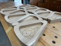
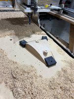
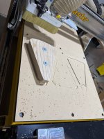
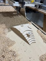
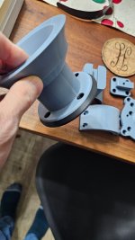
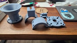
I thought hard about how to do this well with machine-like tolerances for a long time (given that there isn't much room for error with qty. 9 - 3" deep miters per horn) - what I came up with is using the dowel alignment pins as my absolute "home base" registers for everything. The first thing I did was cut the blanks out of ash slabs, and the first operation was locating the two 1/4" dowel holes. Then, I milled into the spoil board holes and put 1/4-20 brass threaded inserts INTO the table, so that for most of my critical operations I could bolt the piece directly to the table with 1/4" bolts - same diameter as my dowels (see first photo below). That way I knew I was dead-nuts on whenever I had the piece bolted to the table. I also created a male-end to the backside of the back petals, because those needed to be flip milled, as the gap between the backside and the bolts gave a tiny bit of wiggle room - with the negative, there was no movement at all. On the operations where I needed to mill a piece that would interfere with the dowel / bolt locations, I did the bulk of my milling around the bolts first - and only after I had the critical parts finish milled (namely, the miters), I would put down wedge-clamps, remove the bolts, and just spot-mill those locations to finish it off (see last photo). Finally, the dowel-alignment pins allow me to have a register to glue-up the top and bottom halves of each petal, as the Z-depth on my CNC wasn't deep enough to mill the entire thing at once.
Perhaps most critically I laid out the whole operation virtually first, so I could understand it really well before I attempted in on the CNC - I use Rhino, and it was a great program for understanding all of this (as well as the design).
Attachments


Makes me wonder how many measurements are flattered out there... good to have found out about this phenomenon though. It does not change my subjective listening pleasure knowing this, and other audiophile friends seem to like it too. Some won't like it, I don't care.In any case, the results show that measuring close and using the mouth as the center of rotation do indeed make a horn like yours appear less "beamy".
Both of them are nearly ready, Thursday is the measurement day.
I take horns to a special stand in the room where there are no boundaries in any direction for 2 meters to the horns. The ceiling is 454cm high. So, I can easily cover the whole band of the horn and see if there is a difference between 60cm, 1m or 2m gated measurements.
I take horns to a special stand in the room where there are no boundaries in any direction for 2 meters to the horns. The ceiling is 454cm high. So, I can easily cover the whole band of the horn and see if there is a difference between 60cm, 1m or 2m gated measurements.
Attachments
I purchased a CNC router and a 3D printer and am learning how to use both. I have purchased most of the files that @mabat has on the Cults platform and chose the ATH-280EX-MK2 as my first print. I am fairly happy with how it turned out. My plan is to build pretty much every design and try them out. For economics sake, I would like to purchase one driver to use on the 260 and upsized models and one for the Tritonia's. This is, of course, unless one driver could do everything. I don't mind spending money to get a really good driver if it can be used everywhere. Thanks for fielding the newbie questions.
Mickey
Mickey
Attachments

The black prints look excellent! What printer did you use?and a 3D printer
And is it fuzzy skin?
I suppose it looks fuzzy where the overhang increases.The black prints look excellent! What printer did you use?
And is it fuzzy skin?
I was playing with ROSSE numbers to get wider HF coverage. The result is for 1 inch driver. For 3/4 inch I could simulate 140 degrees -6DB coverage up to 16000Hz. By using unusual numbers the throat got sharp edges. I think this helps to widen coverage. The question is can throat extension have negative angle to get 3/4 exit? Will this design sound good?
R-OSSE = {
R = 157
r0 = 13
a0 = 57
a = 57
k = -0.36
r = 0.6
b = 1.6
m = 1.7
q = 0.79
tmax = 1.805
}
Throat.Ext.Length = 25


R-OSSE = {
R = 157
r0 = 13
a0 = 57
a = 57
k = -0.36
r = 0.6
b = 1.6
m = 1.7
q = 0.79
tmax = 1.805
}
Throat.Ext.Length = 25
I did the glue up lastnight using PU foaming wood glue - seems to have glued really well but i put too much on i guess and the support shape mould structure thingy to hold it all together was glued in there really well 😀
i got it out with a chisel but there is a fair amount of glue still so i was going to ask you guys what is the best way to get rid of all that? acetone or just sanding it?
i tried warm water and soap and i think it is too dry now for that to work.
next time i guess i just need to use a bit less glue or i might put something like a bit of cling wrap between the shaping mould and the petals?
This looks pretty usable as is, if ugly, so that is exciting!
Last edited:
- Home
- Loudspeakers
- Multi-Way
- Acoustic Horn Design – The Easy Way (Ath4)