What about the dampening factor? Weltersys was explaining this to me. Once you go so high in resistance of the coils your amplifier starts to lose control of the cone creating another type of distortion.Any method lowering the distortion of a loudspeaker is of great help.
Pretty sure everything we are doing is a hobby and a luxury and it can all be chocked up as "trivial". Pretty sure most of our wives and girlfriends consider everything we are doing here as trivial.Unbelievable that such a "trivial" thing can be discussed page after page.
Don´t you want good sound?

No one is talking about modifying an existing design.If you design from scratch all this can go into the calculation.
Its something different changing existing designs
Everything I have I made.
The question is if the added sitoetion from an I core is worth it for the better sensitivity and, as I have just learned, better damping factor
I forgot to mention that this woofer is a dual voice coil. I currently have it wired to 8 ohm but I could wire it to 2 ohm..... then the inductors would be a fraction of the size.
I'll have to run that tomorrow and see what the XO would look like. Might become too low
I'll have to run that tomorrow and see what the XO would look like. Might become too low
Same for most of us, but this is "over my head".Pretty sure most of our wives and girlfriends consider everything we are doing here as trivial.
How in hell can you discuss coils as a problem in general?
No offence, but more fun with building and combinations of drivers.
Higher-order crossover is better in suppressing off-axis cancelation. But it is very difficult/impossible to correct the wrong design with elaborate/complicated crossover. The main problem in your design is horizontally offset mid planar driver respective to the tweeter. It is much easier to start with good design: tweeter strictly vertically above the mid planar driver - then horizontal off-axis cancelation will be zero and simple second-order crossover will suffice.Yes, your off axis is much worse. I am going to notice that even just sitting in my chair.
I lowered off-axis cancellation between 1 and 2 kHz in my crossover with addition of simple RC leg (12 ohm + 3.3 uF) parallel to woofer inductor:
To compare the horizontal off-axis cancelation - below is your fourth-order crossover:
I am not sure what do you mean. Thin wire increases inductor resistance and decreases woofer efficiency - cost sparing here is a bad idea. But lowering resistance of the inductor with the use of iron-core is a good idea. Lower cost too, compared to air-core inductor with the same resistance.@Sonce
If you use thin wire air cores using the resistance at profit in the calculation of the crossover design it spares money. End result can be quite different than use of low resistance coils.
Keep in mind that there are TS. parameters that actually determine just how much improvement can be achieved with HIGH DF.
There are some driver/box situations where a degree of inductor DCR can actually give a 'relative' bass boost just where needed.
PS.
It is my opinion that when it comes to fourth-order filtering > active is much better than passive.
There are some driver/box situations where a degree of inductor DCR can actually give a 'relative' bass boost just where needed.
PS.
It is my opinion that when it comes to fourth-order filtering > active is much better than passive.
Last edited:
My two pennies on the inductor issue is that this speaker will be used near field and not expected to go very loud.
The amplifier will probably never be called on to output more than a handful of watts so even low impedances shouldn't be a problem unless it's sub 2 ohm.
As the speaker won't need to go very loud then the wasted amp power into the high DCR inductors isn't really an issue either.
The biggest concern, imo, is the modification of the bass drivers T/S parameters by any added series resistances.
Hi all,
Might come as a shock for many, but I'll claim a voltage amplifier has never control over a cone, because current is what makes force in driver motor and controls the cone, but the current is determined by the driver + any impedance network between driver and the voltage amp. The amp controls only voltage, which turns into current depending on the load. When impedance in series with the driver is low, the driver is fully controlling current and dampens itself, controls itself, and even that happens only around main resonance where spring cancels mass, not the whole bandwidth because of mass being accelerated. Damping factor of amplifier is thus misnomer, low output impedance of an amplifier (high damping factor) describes how well the driver dampens itself electrically if the amplifier was only impedance in series with the driver, iow a short circuit between driver terminals.
So saying that a voltage amplifier has control is myth, and wrong, but it is what circulates on the forums on both with more and less experienced people. It's quite the opposite, only when amplifier controls current through voice coil, iow has very low damping factor which means very high output impedance, the amplifier would be in full control of the current and thus also the cone, and only then. This would prevent the driver dampen itself electrically at resonance though, unless you manipulate impedance network between amp and the driver and give control of current to the driver, electrical damping 😉
Anyone can come up with this, if you start to question stuff, like why there is relative bass boost with high DCR coil in series? or why would someone say distortion is reduced with high DCR coil? and whether it's true or not, or a sliding thing as everything in analog world? between extremes of black and white there is plenty of gray area in between. When you have found questions and answers, you'll know how a driver actually works and it becones trivial thing to see how amplifier output impedance and any impedance in the circuit with a driver affect in electrical and acoustic domain, what's the relation of the two domains, why enclosure and damping material show up in electrical domain the way they do. Choosing a suitable coil or any other part of loudspeaker becomes almost trivial thing. So, dig in how drivers, a transducer, works. Have fun imagining it through!🙂
ps. voltage amp could control a cone if there is motional feedback, which kinda turns it into current controlling kinda, because one has to control current to control the cone.
Last edited:
For the woofer xo in my 3-way speaker I used inductors with the lowest resistance and distortion I could find,
those are the Mundorf MCoil CFS10 iCore, they have a foil of 70mm (=very low DCR).
For woofer xo inductors above 1mH you're better off with iCores than aircores,
because to keep DCR low in aircores, very thick wire diameter is needed.
those are the Mundorf MCoil CFS10 iCore, they have a foil of 70mm (=very low DCR).
For woofer xo inductors above 1mH you're better off with iCores than aircores,
because to keep DCR low in aircores, very thick wire diameter is needed.
That is exactly why high impedance amplifiers (or high DC resistance coils) can not be used with woofers - there will be a huge peak at woofer resonance frequency. Although current drive is good solution for midrange drivers, it is unusable for woofers.when amplifier ... has very high output impedance, the amplifier would be in full control of the current and thus also the cone, and only then. This would prevent the driver dampen itself electrically at resonance though,
Last edited:
My camera resolution, and hand writing lead you astray. That should be a .5mH coil on the mid, not a 5mH. The dot blended into the tail of the number 5. I didn't notice it looked that way initially. I later saw it, but figured you would catch it.Inserted. What am I missing here? This seems far off.
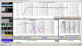
Start with about 20 degrees off axis, and then go about ten degrees each way, The variation is not bad, using the 7 degree frd files. So 7 degrees to about 30 degrees is a listening window. .The direction probably matters a lot, but I couldn't tell which way my software was indicating.
Last edited:
Yeah, but as always there is plenty of gray area, which is why I'm talking about understanding and manipulating impedance instead of using voltage or current amplifier, because the amplifier is basically irrelevant, only circuit impedance from driver perspective matters. One could enable electrical damping at the resonance and kill the peak by manipulating circuit impedance with passive components regardless which amplifier output impedance there is. This would come with it's own drawbacks of course.That is exactly why high impedance amplifiers (or high DC resistance coils) can not be used with woofers - there will be a huge peak at woofer resonance frequency. Although current drive is good solution for midrange drivers, it is unusable for anything else.
Thus, "the current drive" could be useful for bass or mid or treble driver, except perhaps not at drivers main resonance as you say it would make a peak in frequency response. In addition the peak could in theory be damped mechanically, or with filters before amplifier. So, this stuff is quite malleable to any use case, and depends on what one is looking for, what he budget is, what amplifier there is and so on, what ever is the useful and correct way to handle things at any given context.
For this reason I suggest to forget about the amplifier, it's damping factor altogether to be able to think it through and use as design freedom rather than a good or bad thing. Amp output inpedanse needs to be taken account but this stuff is not about the amplifier, but about the driver, how the transducer functions within the electrical circuit (impedance network) it's at.
Last edited:
OK, so please post that magical crossover schematic here! Hic Rhodus, hic salta!One could enable electrical damping at the resonance and kill the peak by manipulating circuit impedance with passive components regardless which amplifier output impedance there is.
Here's eleven to thirty three degrees. Note that I don't show coil dcr, but typical values were included ranging mostly between .3 ohms, and .5 ohms. I changed the tweeter slightly. The 7 degree frd showed the top end a little hotter than the on axis. Anyway, the main reason this might work, is the lower tweeter x-over point. I tried to make this work at very high frequencies, but the range around 10k was not cooperative.
Just noticed. The 10uf cap in the mid filter should be 18uf.
My thinking is that as you move around at your desk, you may go from 20 degrees to 10 degrees on one speaker, and from 20 degrees to 30 degrees on the other. These were using the 7 degree frd files. I didn't have the others to try.
Just noticed. The 10uf cap in the mid filter should be 18uf.
My thinking is that as you move around at your desk, you may go from 20 degrees to 10 degrees on one speaker, and from 20 degrees to 30 degrees on the other. These were using the 7 degree frd files. I didn't have the others to try.
Attachments
Last edited:
Here is a driver in a simulated box, low output impedance in the generator as it would be with our high damping factor amplifiers, so the response is familiar to all, right.OK, so please post that magical crossover schematic here! Hic Rhodus, hic salta!

Here is output impedance of the source jacked up greatly, and the response changes.

Here is the magic crossover, it makes low impedance path between driver terminals enabling some electrical feedback.

- Home
- Loudspeakers
- Multi-Way
- Air Core vs Iron Core - Sensitivity