To me it looks very smooth 0-15 deg up to 3 kHz. Similar to what's seen in your measurements.Thanks! Do I see correctly that there are some midrange wiggles as well?
I do roughly 0-10-20-30 deg and when zoomed in, this should be clearly visible.
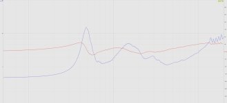
Impedance A520 horn with JBL2453 driver.
There are some imperfections from the assembly and the printing but overall quite good compared with most printed horns Ive seen online. The distortion graphs do not show any obvious problems but I would have preferred to be able to thighten the whole structure together a bit more.
Attachments
Last edited:

To me, those little "bursts" seem to correspond to diaphragm break-up modes (or the compression cavity). Otherwise the midrange response is very smooth.
What adapter is that?
What adapter is that?
Last edited:
Black Bambu Labs PLA-CF and Azurefilm Silk gold.
That Z-layer seam inside the adapter is hard to minimize so I have decided that its not a fault, its a feature.
That Z-layer seam inside the adapter is hard to minimize so I have decided that its not a fault, its a feature.
Haven't you tried a fuzzy surface? I wonder how it would end up with a silk filament (and a random seam, perhaps).That Z-layer seam inside the adapter is hard to minimize so I have decided that its not a fault, its a feature.
Holy ****. That looks fantastic.Its your JBL 2450 adapter.
I have a throat probe ready - now I'm really curious what can be gathered with this.

Regarding electrical damping at the drivers resonance: I bet similar physics are at play as with a woofer, which can audibly ring at resonance if there was high impedance preventing electrical damping. Posted a fun test on another thread that describes ringing sound when no electrical damping 🙂
Just few minutes ago I did fun experiment with closed box bass. If I just drum the cone with my bare hands there is distinct boom to the sound, like a drum, which also blooms audibly if I drum the baffle. This was driver unhooked, and there is no passive impedance network. Now, shorting the terminals, or connect it to an low impedance voltage amplifier, the boomines goes away. Use the other hand to drum and short the driver with another and it's very easy to notice. This is electrical damping, so for a boxed speaker it seems to be better to maintain electrical damping at resonance.
I have had very good results with the scarf seam joint in orca slicer. I would recommend to try it out.Black Bambu Labs PLA-CF and Azurefilm Silk gold.
That Z-layer seam inside the adapter is hard to minimize so I have decided that its not a fault, its a feature.
If "horn loading" means a high acoustic damping (even dominant over the electrical one (?)), then this damping has an obvious problem of not being constant. The degree to which this has an effect on radiated sound and its subjective perception is still not clear to me.
Borrowing the 2452SL compression drivers from a pair of JBL VP7212 I measured two of my A520 prototypes. Both used Mabats JBL2450 adapter which is a perfect (at least physically) fit. The measurement where taken with the middle of the horn at 90cm above the floor. There is a picture of the setup in an earlier post. Gating at 4ms, 24dB smoothing. I also screwed out one of the JBL PT waveguides to compare. Worth noting that the JBL waveguides are not designed for free standing operation.

Feel like Im spamming the thread but here is a pic of an actual system playing music. A520 prototypes. Boxes are JBL VP7212. Horns mounted on top. X-over at 550Hz so C-C is not as crazy as it seems.
Too late to play loud but sounds promising with crossovers created in Audiolense. When measuring the horns at 110dB the distortion stayed low even under 500Hz.
The TV is 65".

Too late to play loud but sounds promising with crossovers created in Audiolense. When measuring the horns at 110dB the distortion stayed low even under 500Hz.
The TV is 65".
Last edited:
Looks like a typical high pass response to me. Here's a (very) rough approximation with digital filters:How do you interpret my impulse response?
Magnitude and phase:

Impulse:

4th order butterworth high pass at 430Hz and single pole low pass at 4kHz.
I think it's low damping the higher the electrical impedance is spiking above Re and Le, the diaphragm moves more easily "than expected". Basing on the current-drive article I linked earlier I think the electrical damping would function only when force affecting the diaphragm turns directly into velocity, iow when spring cancels the moving mass. This happens at least at the system resonance. If the mass is cancelled also by the acoustic loading I guess electrical damping would dampen that as well. On a quick think the acoustic loading likely affects the spring and not mass though? I've not dug into this acoustic loading thing yet to fully understand how it plays out.If "horn loading" means a high acoustic damping (even dominant over the electrical one (?)), then this damping has an obvious problem of not being constant. The degree to which this has an effect on radiated sound and its subjective perception is still not clear to me.
So I think the electrical impedance peaks show where the diaphragm likes to resonate, but doesn't necessarily mean electrical damping does anything to it, except at and around the main resonance frequency for sure. The high acoustic loading bandwidth could resonate due to external excitation, perhaps enough making some distinct sound signature, like boomy drum sound in my drumming test with a woofer.
While this is speculation, it would be a fun test for sure to try and find out whether it matters or not. Since throat adapters manipulate the loading without much effect in directivity, I think this is relatively easy listening test to figure out whether there is audible trade-off with the loading (a resonance due to external excitation that makes audible sound signature), with or without electrical damping using high pass cap and compensating frequency response with DSP. It seems plausible, since external sounds show up in the electrical impedance plot meaning they affect the diaphragm, and reasoning from high electrical impedance due to acoustic loading further indicating the diaphragm moves quite easily, which might make distinct audible sound like woofer drumming test indicates could happen.
Last edited:
- Home
- Loudspeakers
- Multi-Way
- Acoustic Horn Design – The Easy Way (Ath4)