Well done.
If you managed to incorporate a fast acoustic simulation into the Grasshopper loop, you would be king 🙂
To me, "testing" would mean either a simulation or measuring a prototype. How fast can you do that?In any case, it allows for super fast iteration and testing, which is exciting.
If you managed to incorporate a fast acoustic simulation into the Grasshopper loop, you would be king 🙂
It seldom brings any real (acoustical) advantage, honestly. But it looks cool.[...] with the segments being able to be pleated or shaped (if that's a good thing or not I literally have no idea - its just geometry to me)
Last edited:
BTW, I've finished the How-To for the BMS 4554 adapter, it should be usable: http://www.at-horns.eu/gen2-4554.html
I'm quite eager to hear your experiences, as I think this (i.e. Gen2+4554 adapter) is really good.
I'm quite eager to hear your experiences, as I think this (i.e. Gen2+4554 adapter) is really good.
Last edited:

The long shape of the 4554 extended throat makes it basicalle impossible to insert a midrange within 1/4 wavelength. Within this region the horn expansion is still very small.
What happens if they are NOT placed within 1/4 wavelength of XO frequency? Active crossed with matched delay of course. For passive the reasons are obvious why this should be avoided.
Some reflection will happen but thr CD also still supports a bit....
What happens if they are NOT placed within 1/4 wavelength of XO frequency? Active crossed with matched delay of course. For passive the reasons are obvious why this should be avoided.
Some reflection will happen but thr CD also still supports a bit....
Why should it be a problem? It seems that in a case of a coaxial compression driver nobody ever mentions this.Within this region the horn expansion is still very small.
Bad things happen 🙂What happens if they are NOT placed within 1/4 wavelength of XO frequency?
I have to measure it on CAD later but for your adapter at 90mm the diameter was still around less than 50mm. If I insert there a midrange with significant port area I basically disturb everything on the HF wavefront...
Sure, you would have to be careful. But maybe it's just a wrong idea indeed, I have no experience with this.
Well, λ/4 for 600 Hz is ~14 cm. Perhaps you should be still fine this far from the phase plug.
Yes, that drawing looks right. And everything considered it's probably not negative now I see. Although how to calculate!"negative expansion" - I doubt a bit that the area would actually decrease. I found a drawing here - is it this?
View attachment 1395335 View attachment 1395340
It's hard to tell what the wavefront area expansion is. One could at least calculate the total area of the input and the output quite easily. Maybe it's a linear change in between then (in this case), I'm not sure.
I suppose it might all come apart - but not from the exit side - would need all dismantling. And I kinda decided to sell them...
It kind of goes against the idea of extending the throat anyway. Why would you extend it for a MEH? Just use a short adapter in that case. Or a different horn altogether.
My opinion is that the vertical issues associated with noncoincident sources crossed around 600 Hz are actually no big issues at all. I would not sacrifice anything above 600 Hz just to improve the small region around 600 Hz. It just makes no sense to me.
I don't know of any solution that would only improve everything even further.
I don't know of any solution that would only improve everything even further.
Last edited:
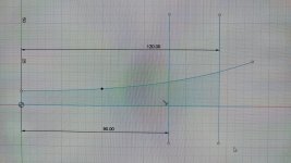
You mean little expansion at 120mm length?I checked before for xo 700hz based on your adapter. You see....not much expansion there. Ignore the 90mm..
In post #16270 I've sketched a 2:1 combiner for the 5530ND, without expansion because that just easy to draw by hand. The extension length outside of the driver was 67.048mm. Expansion could start after that.
Later I fooled around simming a loft that is circle-triangle-circle instead circle-semicircle-circle and the one with a triangle had a better looking response 🙂
Is there any easy attempt to check horizontal Dispersion match vor 8/10/12" LF driver? Not much beaming in that region anyway...
Assuming the side mounted low (midrange..) cone drivers output output is time aligned with delay to the high frequency compression driver, the on axis distance being more than 1/4 wavelength apart is not an issue.The long shape of the 4554 extended throat makes it basicalle impossible to insert a midrange within 1/4 wavelength. Within this region the horn expansion is still very small.
What happens if they are NOT placed within 1/4 wavelength of XO frequency? Active crossed with matched delay of course. For passive the reasons are obvious why this should be avoided.
That said, if the low entrance ports are more than 1/4 wavelength apart from each other horizontally, off axis response will have dips and peaks not conforming to the on axis response.
- Home
- Loudspeakers
- Multi-Way
- Acoustic Horn Design – The Easy Way (Ath4)