Right,I am with Marcel, class C, there is no output stage bias.
Stuart
and that's traditionally called class B - class C is for switching operation only. Just by the way, but of course I understand Marcel. It's just a question of definition.
This is the crux of the matter and also the usual narrative style.The class AB circuit is not suitable for mass production, as the quiescent current depends on the matching between four different types of semiconductor devices. It can easily be solved with a VBE multiplier, but then you have the trimming point back.
https://www.manualslib.com/manual/407305/Quad-405.html?page=5#manual
The simulations say nothing about how well or how poorly the feedforward distortion compensation works as you compare two different output stages, one in class C, the other in class AB.
With the same schematic there s no difference once the OS is biaised at 15mA without FFWD.
Think about it, there s roughly 100db NFB in the Quad 405, at the time most amps had only 70-90dB OLG for at least
26dB CLG and hence only 44-64dB NFB.
99.9% of the 70-80s amps are AB, if that s not mass production then i dont know what it is,The class AB circuit is not suitable for mass production
something like 100M, if not more, were produced in the 70s, just in Japan it was about 160k/month in 1972.
With a CFP there s only the driver VBE to consider, so for an EF2 + CFP there s 3 junctions at play.as the quiescent current depends on the matching between four different types of semiconductor devices

To add to the confusion:
- A Iq greater than the maximum required peak load current
- AB Iq less than the maximum required peak load current but greater than 5 to 10mAdc
- B quasi Iq = 0 mA, for battery-operated, mobile devices
- C currentless, there is absolutely no Iq, switching operation
This is the common European definition!
We all know now, at least since Douglas Self, that the British idea of the optimum BIAS bias voltage leads to B operation. AB is everything between this definition of B operation and A operation.
Not a single Quad current dumper 405 is really C, but always B, optimally prebias it would already be an AB. According to Self, however, a B, for Marcel a C.
perfect world of audio,
kindly
HBt.
☕
When you look in old valve datasheets for audio power valves, you usually see a recommended bias point with a fairly small but nonzero anode current that is referred to as class B and a recommended bias point with a higher anode current that is referred to as class AB. Sometimes there is a distinction made between class B1 and B2, depending on whether the valves are driven into grid current in the signal peaks.
Douglas Self calls it class B when the output stage is biased at some small but nonzero current that results in a distortion minimum - or at least that's what he did 30 years ago. Class AB then refers to a higher than optimal quiescent current. I think his use of the term class B is consistent with the original valve-age meaning of class B (class B2 for bipolar transistors and class B1 for MOSFETs). A disadvantage is that it is unclear what class B means when the output stage has no distortion minimum.
The reason why I chose to call the case with a quiescent current class AB rather than class B is because others call it B when there is no quiescent current. I did not mean to imply that the quiescent current is larger than optimal.
It think a stage with a dead zone fits best with the definition of class C, although you could argue that only one side of the dumper is really in class C, because the other side conducts a quiescent current. The usual definition of class C is that for a symmetrical waveform, the output devices conduct less than 50 % of each period.
99.9% of the 70-80s amps are AB, if that s not mass production then i dont know what it is,
something like 100M, if not more, were produced in the 70s, just in Japan it was about 160k/month in 1972.
I think most of them had provisions to adjust the quiescent current. The second circuit of post #97 has no such provision, which is why this specific circuit is not suitable for mass production. It can easily be solved.
With a CFP there s only the driver VBE to consider, so for an EF2 + CFP there s 3 junctions at play.
Four is indeed incorrect. There are six semiconductor junctions of five different types involved:
2 times 1N4004
BY229
BD139
MJ15022
BD140
Has a Quad405 been the big hit in the amplifier world, especially compared to the competition? Apart from that, feedforward & feedback, i.e. pfb & nfb, is an interesting thing ..!
@wahab
If you implement the missing R and L for complete current dumping - what is then the final THD (or FFT)?
@MarcelvdG
Could you add your modifications to the 405 as a schematic to complete this thread?
greethings,
HBt.
Psst
I'dont like the schematic of Quad's 405, with the strange "PI-Regler und schlechte, kombinierte Offsetkorrektur am Eingang, Stromsummierung!".
'wahab' mean the pn-junction of Q3, Q6 and Q7 so three diffusion voltages must therefore be overcome or pretensioned.Four is indeed incorrect. There are six semiconductor junctions of five different types involved:
"1N4004
1N4004
BY229
&
BD139
MJ15022
BD140"
Are you worried about poor thermal matching/compensation?
Rather about an unpredictable quiescent current. The five different semiconductor types in the loop all have their own process spread, all independent of the others as they are of different types made in different factories. As a result, there is no way to predict the quiescent current. Replacing the diodes with a VBE multiplier with a trimming potmeter can solve that.
Once that is solved, you still have the variations with programme dynamics due to imperfect thermal tracking. The MJ15022 output transistor will heat up more than the VBE multiplier.
Once that is solved, you still have the variations with programme dynamics due to imperfect thermal tracking. The MJ15022 output transistor will heat up more than the VBE multiplier.
Could you add your modifications to the 405 as a schematic to complete this thread?
I don't know what modifications you mean.
I refer to your earlier reply about the OP amp, the integrator and the offset story, or the better, lower-noise correction ... or something?!
But never mind,
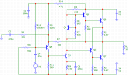
in the last few hours I have taken the standard circuit of the late 1960s as an opportunity to feed MC12 as a precaution. I use BC546B, BD140 & BD139 as well as MJE802, a VBE multiplier with the BC547C recessed between the cooling plate of the end transistors of the same conductor type. R13 and R7 are considered trimmable. Iq exactly 30mAdc.
Now the THD_1k always remains below 0.01%, the famous bathtub has a depth of 0.001% ... why do I need the dumper mode now ???
A Revox A78 doesn't need a current dumper either - and (btw) I love this amplifier.
greetings,
HBt.
😎☕
But never mind,
in the last few hours I have taken the standard circuit of the late 1960s as an opportunity to feed MC12 as a precaution. I use BC546B, BD140 & BD139 as well as MJE802, a VBE multiplier with the BC547C recessed between the cooling plate of the end transistors of the same conductor type. R13 and R7 are considered trimmable. Iq exactly 30mAdc.
Now the THD_1k always remains below 0.01%, the famous bathtub has a depth of 0.001% ... why do I need the dumper mode now ???
A Revox A78 doesn't need a current dumper either - and (btw) I love this amplifier.
greetings,
HBt.
😎☕
Attachments
Actually the original definition is class A, always conducting, class B conducting 50% (or 180 degrees), class C less than 50%. If you don't bias a push-pull transistor circuit it is class C (certainly for low voltages), as there are significant times when neither device conducts. A class B output correctly biased will have each device conducting 50% of time (averaged over the cross-over).Right,
and that's traditionally called class B - class C is for switching operation only.
It gets rather grey at higher voltages where the +/- 0.6V hysteresis is a very small part of the waveform. AB was defined I think for various push-pull tube circuitry, and in theory means conducting > 50% of the time.
I think most of them had provisions to adjust the quiescent current. The second circuit of post #97 has no such provision, which is why this specific circuit is not suitable for mass production. It can easily be solved.
For such sims i dont bother with exact thermal stabilisation since that s not the point under scrutinity.
Four is indeed incorrect. There are six semiconductor junctions of five different types involved:
2 times 1N4004
BY229
BD139
MJ15022
BD140
The CFP Iq is set by the driver since the power device is enclosed in its local FB loop, so there s 2 devices whose
Vbe decrease by 2mV/°C but this is over compensated by the three diodes, wich happen to also compensate
the beta variation, believe it or not, Iq is exactly 16.92mA at 27°C and increase to 17.68mA at 60°C.
Other than this in the original 405 the upper device is -600mV reverse biaised, wich set it in a slight class C mode,
they added a diode in the 405-2 to get it 60mV forward biased and this logicaly decreased THD but also increased
the VAS current from 60 to 75mA.
@wahab
If you implement the missing R and L for complete current dumping - what is then the final THD (or FFT)?
Buffering the upper device of the original schematic change nothing to THD, also the H2 high level is to be discarded
for analysis as it can be adressed with a few mods, what matter is the level of H3 and higher harmonics when estimating
the error correction.
Thank you from the bottom of my heart, this was something I had no longer had on my radar.Other than this in the original 405 the upper device is -600mV reverse biaised, wich set it in a slight class C mode, (...)
Thank you, thank you ... this is CLASS C “the real switching mode”.
regards,
HBt.
You re welcome, but this apply only for the upper part of the amp, in the negative side for the 1975 Quad 405 the driver supply
22mA since these are necessary to feed the IPS emitter with 5mA and balance the 17mA positive current that flow out of the FFWD resistance, the (negative side) power device providing only a few dozen uA.
In the revised 1978 Quad 405-2 version the driver current is increased to 29mA while the power device is switched on with 8.6mA bias, so the whole is a positive side power device more or less in class C and a negative side that is in class AB.
This does not contradict my statement, it expresses exactly the same thing - with the reference to the unit-circle and the angle.Actually the original definition is class A, always conducting (oder 360 Grad), class B conducting 50% (or 180 degrees), class C less than 50% (oder 60 Grad).
If anyone now have problems with understanding different convolutions, I recommend "Valve Amplifiers by Morgan Jones" pages 441, 442 & 443 (fourth edition, Newnes).
#
Incidentally, it should also be noted that current dumping actually works - As jxdking's other thread on this vividly demonstrates.
Bye,
HBt.
what really counts(...) what matter is the level of H3 and higher harmonics when estimating
the error correction.
deltaTHD |9dB|
suddenly only 2.8 times the almost 20-fold improvement remains. Nevertheless, the odd multiples are significantly weakened, the proof is there, but whether this really has any practical relevance is written in the stars.
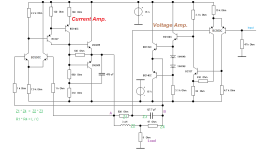
If you could, you could also design two completely discrete operational amplifiers. One (the one on the left) with plenty of crossover distortion and switching characteristics and another (the one on the right) with a class A PP output stage. This makes the dumper principle much easier to recognize.
That would be worth an investment?
That would be worth an investment?
Attachments
... the above "dumper for dummies" can never really feedforward-correct a real class B power amplifier (almost currentless).
The current source of the Matsushita Class AA concept and the Voltage control Amp. do this with ease. That is the difference. An illustrative, I admit: mean example.
The current source of the Matsushita Class AA concept and the Voltage control Amp. do this with ease. That is the difference. An illustrative, I admit: mean example.
Attachments
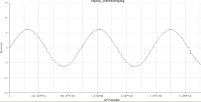
Let's just take a look at the spectrum of a 2.5Wrms output of a profane push-pull power amplifier in (real) B mode (no AB):

Our NFB is now supposed to reduce a very unpleasant distortion factor of 6% to perhaps 0.06%. And with the help of a magic air-core coil and a small bypass resistor working dynamically in parallel, we want 0.0006% ---> that doesn't work!
Our NFB is now supposed to reduce a very unpleasant distortion factor of 6% to perhaps 0.06%. And with the help of a magic air-core coil and a small bypass resistor working dynamically in parallel, we want 0.0006% ---> that doesn't work!
- Home
- Amplifiers
- Solid State
- Current Dumping with OPAMP