Yes, and then a ground loop breaker. And gather those ground wires into one connection point, instead of leaving two inches between them as loop area.
The current setup is bound to hum. And remember: the ground loop breaker / resistor DOES NOT go between PSU and amp boards, but between PSU and chassis.
As a quick test to help troubleshooting, simply disconnect the wires from the VRDN to chassis. Listen, any difference? Then, gather the grounds to each VRDN into one socket instead of spreading them around. Then, put a wire between the two BA2018 halves’ ground sockets, and listen. Quiet now? If not, look elswehere than grounding issues for faults.
If lifting the chassis connections by and itself solves it, use a GLB. A simple resistor may not solve it.
Btw: have you tested the BA2018 circuit and confirmed it works as it should, noise free?
Do this systematically. From your follow up posts, it is difficult to discern what you have and have not done.
PS: One channel at a time.
Hugz and spanks,
Andy
Last edited:

Right channel, run alone, wow, finally quiet. Add in another resistor to the left channel, power it up and...noise returns to both channels. So geez, there is some dark voodoo going on when two or more VRDNs are up and running. Will ponder off into the darkness...I'm still missing something.
If the right channel run alone is quiet that is a start.
Things to try:
-Left channel run alone. Quiet or noisy?
-Right channel with left channel power supply, run alone. Quiet or noisy?
-Left channel with right channel power supply, run alone. Quiet or noisy?
Hi everyone. Great thread! I just finished this build and doing some final checks and noticed that I'm getting 14v at one of the outputs. I was able to get the other side down to zero using P1, but no matter how much and in which direction I turn P1, i can't get the voltage to drop at all. I've confirmed that the POT works because as I've noticed that making adjustments to P1 changes the resistance on R36. I've checked resistance on all the rest of the resistors and for the most part they're all spot on with the exception of R10/R24 which start at 8k and slowly creep up. this happens on both sides though.
Any thoughts? thanks in advance everyone!
-Thanh
Any thoughts? thanks in advance everyone!
-Thanh
Note: R6 and R36 are smaller because I swapped them out to test. They're good quality 1/4 watt vishays. I'm probably going to put the original ones back since swapping them out didn't resolve the issue
Although things look pretty darn beautiful, touch up the SMD soldering on the non-operative side. That's usually the culprit when you've got lots of DC on the output.
Also check that Q9(Q19) and Q14(Q26) are stuffed with the proper device.
Also check that Q9(Q19) and Q14(Q26) are stuffed with the proper device.
You can look at my comments at #4333 and #4336 to a member with a similar failure mode.
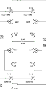
Ohm's Law is a formula used to calculate the relationship between voltage, current, and resistance in an electrical circuit. If we know two of those parameters, we can calculate the third with an extremely simple calculation. Is there any current flowing through Q21, Q22, Q23, and Q24 (and associated components) on your defective board? R35 and R37 would be a fantastic place to check for that. If you know the resistor value, and you know the voltage across it (measure w/ DMM), you can very easily calculate the current through it.
Ohm's Law is a formula used to calculate the relationship between voltage, current, and resistance in an electrical circuit. If we know two of those parameters, we can calculate the third with an extremely simple calculation. Is there any current flowing through Q21, Q22, Q23, and Q24 (and associated components) on your defective board? R35 and R37 would be a fantastic place to check for that. If you know the resistor value, and you know the voltage across it (measure w/ DMM), you can very easily calculate the current through it.
Attachments
Last edited:
Thanks 6L6 - I will reflow/touch them up and report back.
William - I will look at those posts and report back.
William - I will look at those posts and report back.
Good point. I have created a thread so that I can control the first post and keep all tests more organized. It is here:From your follow up posts, it is difficult to discern what you have and have not done.
https://www.diyaudio.com/community/threads/bhjazzs-ba2018-ground-noise-problems.420823/#post-7863441
Although things look pretty darn beautiful, touch up the SMD soldering on the non-operative side. That's usually the culprit when you've got lots of DC on the output.
Also check that Q9(Q19) and Q14(Q26) are stuffed with the proper device.
Thanks for the assist guys. Turns out one of the JFETs was bad.You can look at my comments at #4333 and #4336 to a member with a similar failure mode.
Ohm's Law is a formula used to calculate the relationship between voltage, current, and resistance in an electrical circuit. If we know two of those parameters, we can calculate the third with an extremely simple calculation. Is there any current flowing through Q21, Q22, Q23, and Q24 (and associated components) on your defective board? R35 and R37 would be a fantastic place to check for that. If you know the resistor value, and you know the voltage across it (measure w/ DMM), you can very easily calculate the current through it.
Remote control is also acting up - codes being received but not being processed.
I can't say enough good things about Academy Audio, specifically Dr. Lenny Novikov. He has graciously offered for me to send my ailing MCL unit to him for further troubleshooting. He is fairly sure the entire board is not dead and already has an idea that I may have given one of the chipsets a static charge that removed the instruction set. As I purchased the unit some months past and have had it out of it's static bag more than once, this seems very likely.
At any rate, just wanted to give a thumbs up for Academy Audio. 👍
Hi everyone.
Has anyone found a practical method of incorporating tone control? Things sound absolutely fantastic but the highs are just a tad high. I've looked at so many tone control circuits I'm sick of it. Even drew a passive baxandall based circuit but I think the dB loss would be too great. I reached out to Elliot to see if his project 97 offering would work, he said I would have to replace the output stage of his circuit with the BA2018. I started down that path for now, but it requires drawing and dissecting his schematic (which he has actually already broken up quite nicely) and then figurings out where/how to implant the BA 2018.
I'm interested to know what others of have done (if anything at all).
Thanks!
For something quick and simple, how about a low pass filter at the preamp output. Add a capacitor to ground at the output to work in conjunction with the 27R resistor.
Low pass calculator
Low pass calculator
Has anyone found
if rest of system is on par with Wayne's pre ( sources and amplifier), rather look at your speakers and why there is abundance of highs
better to optimize system than forcing signal through (additional) bucket of mud
BA2018 certainly doesn't "add" anything, it's extremely well behaved and very low distortion as one would expect from one of Wayne's creations. Maybe you could turn your speakers off axis? If they are facing straight at you, maybe try less toe-in, crossing at a point back behind the listening seat instead..
@william2001: And another advantage to straightening the speaker alignment out is that the soundstage improves -- if you are sitting far enough back. Spent years listening to towers toed in so they converged one foot in front of the face (as one manufacturer recommends) and when the speakers were more straight aligned, the soundstage became more coherent and accurate. Give it a try.
- Home
- Amplifiers
- Pass Labs
- Wayne's BA 2018 linestage